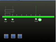
PLC Conveyor Assistance

I agree with drbitboy on using a timer to determine the length of the box. We do this in the plant it work at and it works very well, practically without issue.

Drbitboy gave a good code example. But it's just a framework example.

When designing a system, and indeed when writing a program you should ask yourself what could go wrong, how could it fail, and if there's a better way to do it.


 Sensor1
---] [-------[TON longton ]---
[ DN]---
[Pre LongTime]
[Acc 0]


longton.DN LongBox
-----] [---------( )------


What happens if the conveyor stops?

How do you track which boxes are long or short after the sensor determines the length?
 
As I indicated previously, if the divert station is a distance from the box size detection then you need to use a shift register, There are a number of ways to do this, simply if you cannot have a pulse generated off the conveyor drive (a proximity detecting pegs on the main drive) then use a self resetting timer of a short duration to generate the pulses, use this to shift the box type along the conveyor, although not perfect as any speed variation in the conveyor will not be reflected in the shift, however, for short distances this would be fine. Effectively the array of variables in the shift register are sections of the conveyor. I will post a simple logic to show how it could be done but it may be different in the sim you are using.
 
Here is something I quickly cobbled up in Mitsubishi, it uses only one PE to detect the box length & 1 to detect when it is on the divert, the way it works is a pulse is generated every 100milliseconds to replace having to use a prox on the conveyor shaft (should be good enough on a system where a box would take at least a second or too to pass over the box length PE.
The length is put into a cobbled shift register (hard coded as your simulator I don't think has one).
When a box is detected, it measures the box length in 100ms pulses and puts that count into the first word of the shift register, the conveyor pulse timer shifts the data along the array of words. when the shift register words 5 or 6 contain data then it compares it for fixed values within a range for small boxes or large boxes, in this example a small box is roughly 7 seconds long a long box is 13 seconds long (ignore it being slow, this just helps with simulating so you can see it work).
If the value in the array 5 or 6 is between 33 & 50 then the box is diverted, however, if it is a small box a count of 7 then it is ignored, two boxes will give a value greater than the long box so it will be ignored and allow it to pass without being diverted (this assumes two small boxes will be either smaller or greater in length than a large box, this is only a trial so the values are just random, if this was an actual system then the shift register array may be greater in size, the number of counts from box leading edge to trailing edge would be different etc. I know this works as I did something similar some years ago, I have also done a sortation system that read bar codes on a conveyor put them into a very large shift register (over 1000 registers) and would divert down one of 17 divert lanes, however, that one did use a pulse of the conveyor. I have tried to make the logic pretty simple as I'm aware that the simulator you are using is pretty basic & terrible to use I tried it but given it's limitations you may have to have longer timers etc. as I'm sure it is pretty slow.
 
Hi guys. Sorry for the lack of replies, been a busy couple days. Anyways, I appreciate the help but my lack of knowledge is making me struggle with some of the stuff you guys are saying.

I have to use PLC fiddle and the components on there to design the ladder diagram first so i don't have a lot of the components you guys are saying.
 
Tosh, see part of the code I posted but in PLC Fiddle.
I will send you a Private message with the link to the code, I have not finished it but it will give you a start.

PLC Code.png
 
Here is another way, if the sensors PE01 & PE02 are a set distance i.e. a small box will not cover both but a big box will, then it is possible to detect the difference providing PE01 can detect the small gap between bunched up boxes.
For example if two boxes are together they pass over PE01, it sees the small gap before it reaches PE02 so it knows these is a small box, same goes for any small boxes, however, if a large box passes then both PE's will be covered, by using one shot rising & falling on PE1 & combination of PE02 you can detect the boxes without actually measuring them see below code.

Short Box.png Long box.png
 

Attachments

  • Box Size.pdf
    84.5 KB · Views: 7
... struggle with some of the stuff you guys are saying.

...don't have a lot of the components you guys are saying.

Okay, let's step back a bit.

I) Any computer program is a model of something in the real world.


That is, the computer program manipulates bits (a.k.a. variables a.k.a. memory), which bits represent entities in the real world.

For example, if Sensor1 measures a box and determines that box is 30.48cm long, it might put the 30.48 into a variable (memory) that represents a floating point value; call that variable LEN. Then, if a second box came long that was 60.96cm long, it might put the value 60.96 into that same variable, LEN, overwriting the previous value (30.48). The point is that the rest of the program can check that variable LEN to determine the length of the last box measured by Sensor1.

II) The model implemented by the program does not need to keep track of every piece of the real world


For example, there is no need to model
  • the orbit of Pluto,
  • or oxygen and nitrogen molecules in the conveyor room, individually or in toto,
  • or the state of the light switch in the room
III) The program needs to keep track of every modeled piece of the model, but not to infinite precision

For example, if all of the boxes are at least 30.48cm long, and the pusher is 20.32cm wide, then the model does not need to keep track of what is on every cm of the conveyor; probably 10.16cm should be "good enough."

Another aspect of this is the discrete nature of the model: the conveyor is moving continuously, but the PLC scan happens every few ms, and during any one scan it generally assumes all variables are as last measured i.e. static or constant. Also, the model of what is at each modeled station on the conveyor will only move to the next modeled station for every 10.16cm of conveyor motion; there is no "box overlaps two stations" indication. The programmer always be evaluating whether the model is "good enough," sometimes by engineering judgement, sometimes by experiment.

IV) The program cannot use tools its processor/language does not have, but it can build more complex tools from simpler tools that it does have

For example, one way to represent boxes on the conveyor is as bits in an integer. Each bit's position (0, 1, 2, ..., 31) in the integer could represent each 10.16cm section of conveyor from Sensor1 to the pusher. A 1 bit could indicate that a long box was detected, and a 0 bit indicates that no long box is present*.
xxx.png
* Note that a 0 bit could represent EITHER a short box OR no box; the program doesn't need to discern between a short box and no box, because it does not need to push either; this is an application of principle (III) above.

To represent the motion of the conveyor, the program would move (shift) all of the bits to the next (more significant) position. Most PLCs have a bit-shift instruction to do this; if they do not, the program could multiply the integer by 2, although that gets messy if multiple integers are required. Both techniques (bit shift or multiply) presume the program can assign and examine an individual bit of the integer, specifically the bits that represent the conveyor positions at Sensor1 (to assign a 1 or a 0) and near the pusher (to examine and detect a 1 or a 0).

As an alternative to using bits to indicate long/no-long boxes, a functionally equivalent construct would be an array of numbers: the position in the array represents the conveyor positions; the value in each array element represents the length of the box at the corresponding position, e.g. 60.96, 30.48, and 0.0 for long, short, and no box, respectively. Again, most PLCs have some sort of FIFO (First-In-First-Out) instructions that could be used to shift the integers to the next position to model movement of the conveyor. If not, then the program could leave the array values in place and increment indices into the array to model conveyor motion; one index represents Sensor1 position, another the pusher position.

PLC Fiddle appears to have neither bit shift nor a simple way to examine individual bits in an integer, nor does it have an array, so another way must be found. If you look at @parky's example in post #18, rungs 9 through 14 in the PDF attachment nicely implement a brute-force FIFO: the variables Shift_Reg_0 through Shift_Reg_6 compose a shift register, and it takes six instructions to model conveyor movement i.e. to implement the shift.

Another issue to deal with is modeling the movement of the conveyor itself. There might be a proximity sensor monitory a sprocket's teeth or spokes, which would be best. If not, then if the conveyor speed is nearly constant, the movement can be modeled with a timer. In that case the model moves from the spatial domain (e.g. length from Sensor1) to the time domain (time from Sensor1), and there might need to be some padding or fuzz placed around the various decision points in the model to deal with variations from the assumption of constant time and constant time (PLC timers are non-deterministic) and constant speed, as noted by JTCat.

Conclusion


The essence of programming is to look at the process, and look at the tool (PLC implementation), and then figuring out how to model the former with the latter, including (i) what does not need to be modeled, (ii) what does need to be modeled, and (iii) to what precision.

You kindly said in your OP that you did not want anyone to do this for you, but also that this is new to you. I strongly suggest you check out Ron Beaufort's excellent series of beginning videos here; also study the content at this link, which is one of many places that provides ladder patterns you will use over and over.

Finally, I leave you with some simple patterns as PLC Fiddle rungs below, suitable to the current task. The first is a bit shift triggered by a pulse; the second is a FIFO number shift triggered by the same pulse; there would need to be more of these to shift 1 to 2, 2 to 3, etc.; I leave it to you to determine the order. The third rung assigns zeros to bit and number at the head of the bit shift and number FIFO registers, and only one is needed i.e. to assign the element at position 0; the fourth is a repeating, self-resetting timer, that will work with most, but not all, PLCs.

Note that the pulse MUST have a duration of exactly one scan. I provided the bit shift to show that the MOV to accomplish the number shift is much simpler. You would only use either the bit shift or the number shift, and of course you do not have to use either of these as you may come up with something better.
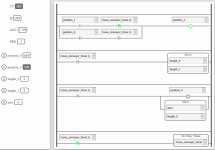
yyy.png
 
You can do small length shifts in that sim but you need to hard code it so the conveyor pulse needs to be say a second or two and only have enough registers in the array to cover the length of the conveyor and be at least the size of the small box say 6 or so (depending on the length of the conveyor) it is just a case of moving array(max-1) to Array(max)
So assume we have an array of 6 elements then it becomes

AND conveyor pulse
Move Array(5) to Array(6)
Move Array(4) to Array(5)
Move Array(3 to Array(4)
Move Array(2) to Array(3)
Move array(1) to array(2)
Move Array(0) to array(1)
As the PLC scans left to right and top to bottom this works
In the code I just posted, just for clarity I put a 1 into the register on a small box & a 2 for a large box, however the 1 is not needed as it is not diverted.
The pics show the simulation where a large box (shown as a 2 in the 4th or 5th registers) and the divert solenoid operating, the other picture shows the small box (1) not triggering the divert.
I also wrote some code on that simulator it's awful, although it does work, have no idea how you are going to test it, I used buttons on an HMI to trigger the sensors and display the registers shifting the data along the conveyor.
 
Last edited:
By the way, we have been assuming the shift register, whether bits (long/not long) or lengths, is modeling conveyor position i.e. the distance from Sensor1.

Since there is Sensor3 at the pusher, if the PLC program can assume that, on initialization, there are no boxes between in the modeled process (i.e. between Sensor1 and Sensor3, then the shift register could be a FIFO that tracks the boxes themselves:

  • the FIFO is empty (length = L is 0) at initialzation
    • L is also the index into the FIFO where the next Sensor1 result is to be pushed
  • P is set to 0
    • P is the index of the next box at the pusher
  • On each Sensor1 falling edge a 1 (long box) or 0 (not-long box) result is pushed onto the top of the FIFO at position L and L is incremented* by 1
  • On each Sensor3 rising edge, the result at index P is popped off the bottom of the FIFO
    • After which P is incremented* by 1
    • If the result is a 1, then the pusher is extended to reject the long box, then retracted
    • If the result is a 0, then the pusher is left retracted
  • If the value of P is LMAX*, then assign 0 to P
  • If the value of L is LMAX*, then assign 0 to L
* The FIFO is an finite array that is long enough to hold one more than as many boxes can be modeled at any moment; call that size LMAX. So "incremented" above is actually a two step process that turns the array into a circular buffer.

The advantages to this approach are

  • It does not rely on constant conveyor speed, which is required if time can be a proxy for conveyor position.
  • If the conveyor stops, the model accurately keeps track of the process with no extra coding, which is not the case with time-as-proxy-for-position.
  • There are a working examples of both approaches here.
One other thing: as @parky notes, PLC Fiddle is very limited; some PLC vendors provide free versions of their software, plus a corresponding emulator; switching to one of those would be well worth the effort; asking The Google about [vendors free plc programming software with emulator] will provide many options.
 
Last edited:
I agree with many of those statements, as there is no actual pulses from the conveyor there is possibility of slip etc. that is why I added two array locations so that would give some allowance for slip as there is a sensor.
Unfortunately for the OP he has to use the on-line simulator according to his posts, also the tutors brief is very poor, without the critical explanation of box sizes it is difficult to come up with proposals to the problems, If the documentation provided stated the box sizes then it is possible to do as I have suggested in the last post, should there be more than two sizes then a different approach is required, i.e. sample the actual box size, I would challenge the tutors reasoning why would you select two different types of PEC this is not good practice in real life. Given such a brief with more holes than a cullender is typical of tutors. Timing should not be a problem a quick change of the conveyor pulse generator pre-set should give a reasonable number of places in the shift up to the reject station to get it aligned, i.e. the number of shifts from measure to divert. yesterday I borrowed my grandson's Meccano set, built a conveyor & used a couple of leggo bricks of different sizes just for fun, wrote the program in an FX3U used 3 limit switches with whisker actuators (did not have any sensors) & it worked well after a bit of fine tuning, quite enjoyed it, last time I used Meccano was in the early 80's when I simulated a waste collection system for a effluent plant.
 
Hi everyone. I'm back and I have found the solution to plc fiddle. I have had to convert it to studio 5000 now but I'm having a problem with a One shot (ONS). I have a one shot that will energize an output which should load a bit into my shift register. However, when the one shot is energised, a bit isn't loaded into the shift register.

I have manually triggered the output and it does load a bit into the shift register but its something to do with the ONS
 
Last edited:
There should be a rule:

Don't let the temptation of using clever control scheme to resolve a mechanical / process shortcoming because you happen to the "control person". Fix the real problem

I want this on a T-Shirt!
People start talkin nonsense, Ill just take off my coat.
 
Hi everyone. I'm back and I have found the solution to plc fiddle. I have had to convert it to studio 5000 now but I'm having a problem with a One shot (ONS). I have a one shot that will energize an output which should load a bit into my shift register. However, when the one shot is energised, a bit isn't loaded into the shift register.

I have manually triggered the output and it does load a bit into the shift register but its something to do with the ONS


Can you show the code that is giving you trouble?
 
Make sure you aren't using that ons anywhere else in your code. Each ons in your program should have it's own bit. For example, create a dint, and only use each of the 32 bits once for all your one shots in the program.

Also, don't use a branch directly underneath the ons, those have given me some problems in RS Logix 5000, but I don't think you are using this software.
 
maybe a shift register is not the most reliable way to track packages to a divert.

sequence number tracking
Most schemes using a sequence number to represent the box, at photo eye, dump this sequence for any measure of length say 1 inch into a Dint[500] long at one end.

You can also generate a fake encoder pulse - 1 inch 1 pulse based on a tached speed of conveyor. Or use an encoder.

Leading edge of box - generate tracking number, use tracking number for an offset into a carton data array. You can use that sequence number to generate reason codes , measure the box, all sorts of things like counts to measure distance between boxes.
During box - keeping putting sequence number into tracking
Trailing edge of box - stop sequence numbers, fill the array track with zeros when the box is not blocking pe.

Just some suggestions.
 

Similar Topics

Need help with designing and test a PLC-controlled pneumatic system that conveys manufactured parts and loads them on a packing machine. I am...
Replies
8
Views
2,636
Hi, I need help in designing a control system for conveyor. The goal is to connect PLC to bar code sensor and then connect plc to serve to...
Replies
1
Views
1,274
Hey I am having issues witb this project im working on and I seem to have trouble on how to approach the objective can someone assist me please
Replies
18
Views
3,143
Good Morning Everyone, I am entry level PLC programmer and this is going to be my first PLC project at my company. I would like to thank you for...
Replies
13
Views
4,177
First off, I am new to the whole PLC world and was tasked with a project at work. I was given a Click C0-11dre-D, Honeywell 310G barcode scanner...
Replies
4
Views
2,294
Back
Top Bottom