SLC 5/04 - 1761-NET-ENI - Powerflex 525`

Thanks for those details ! Some simplified background highlights:

RIO and DH+ share the same signal and wiring but different protocols. The SLC-5/04 has a DH+ port built into the CPU, but can have a RIO Scanner module in any slot (more than one, up to a memory limit).

It's a "Manchester-encoded" signal, where the timing of the rising and falling edges makes a 1 or 0, not the signal level. The signal interface is remarkably tolerant of installation and noise problems, to the point where it really spoiled A-B users for less rugged but faster modern networking.

But time marches on, and the chips aren't economical to produce anymore, so A-B bought their last batch five or so years ago and demand will dictate future prices. Probably there's a batch squirreled away to build PLC-3 and PLC-5 parts for the Dept. of Defense.

The 1747-SN basic functionality is pretty straightforward: it has 32 words of data addressed to the Slot number. For a 1747-SN in Slot 4, the user program has access to:

I:4.0/0-15
I:4.1/0-15
[...]
I:4.31/0-15

O:4.0/0-15
O:4.1/0-15
[...]
O:4.31/0-15

The old RIO addressing scheme used octal "rack" numbers but with the SLC it uses decimal word and bit numbers. Because the 1747-SN only supports four "racks" worth of adapters, octal rack numbers 0,1,2,3 use the same digits as decimal.


When used with AC drives like the 1336 Plus, Plus II and 1305, the basic setup was each drive = "1/4 Rack" of 2 words input and output, but you could also do larger 1/2, 3/4, and Full rack increments.

The first 1305 drive attached to the network would be Rack 0, Group 0, and would be addressed like:

I:4.0/0-15 = Status Word
I:4.1 = Feedback Word

O:4.0/0-15 = Command Word (Start/Stop/Fwd/Rev/Reset)
O:4.1 = Reference Word (0-32767 = Min Hz to Max Hz)

If you wanted to use the I/O image for transfer of other parameters you could set them up two at a time as "Data Links".

If I had to connect just 5 drives to a 1747-SN, I would probably set them up as "1/2 Racks" and configure them for some extra parameter feedback like fault codes. 5 x 1/2 Racks = 2.5 of the available 4 blocks of addressable memory.

But you could simplify them and do just 2 words each as well.

When examining a system I'd start by looking for the Start/Stop bits and seeing which Word of the 1747-SN slot they are in, which will allow me to infer the Rack/Group addressing of the drives without examining the DIP switches. If they're offset by just 2 words (0, 2, 4, 6, 8) the drives are using the smallest data configuration of "1/4 rack".
 
Distributing the drives along a conveyor takes advantage of the distance capabilities of RIO (up to 10,000 feet !) but your 200 foot conveyor is well within the capabilities of other networking technologies.

To my knowledge there is no RIO adapter for the PowerFlex 520 series, nor can any of the old RIO adapters be used with it (20-COMM-R or 1203-GD1).

So as you've seen, you can use Ethernet, RS485, DeviceNet, or even Profibus DP.

There are a handful of ways to skin this SLC-5/04 -> 5x PowerFlex 520 VFDs, of course, depending on your budget and your experience.

The temptation to try a 1761-NET-ENI equivalent out the serial port is there, and it might work, but you need to do some testing or analysis to be sure the speed is quick enough to stop/start/change conveyor speed for the application.

And I wouldn't use the 1761-NET-ENI itself, not only because it's been discontinued but also because it had a small connection capacity of just 4 TCP connections, and you need 5.

Allen-Bradley VFDs do support this kind of command over non-cyclic network messaging where third-party devices would not, specifically and on purpose by implementing emulation of PLC data tables.

To initiate messages on a controller serial port and have them sent to an IP address, you need that Net-ENI specific feature of a DF1 to IP station table. That's a very specific thing that a general purpose Ethernet/Serial device won't have.

The big benefit of using Ethernet for this is that you can run the Ethernet cable now, and make it easy to switch over to EtherNet/IP and ControlLogix later. And the PowerFlex 525 has the built-in port, so no clumsy converters or daughtercards.

The big drawback is that you aren't taking advantage of the functions of a dedicated-purpose module like a 1747-SN or 1756-ENBT and you have to write the messaging logic yourself and be sure it retries, times out, and recovers from failures correctly.
 
A specific question for our Forum colleague "geniusintraining": Does the 1761-NET-ENI Series D substitute have that DF1 / IP routing table, and how many entries does it support ?
 
Does the 1761-NET-ENI Series D substitute have that DF1 / IP routing table, and how many entries does it support ?

Yes it has a routing table and it has the same limitations as the original ENI, so if the old one was limited to 4 then ours will also be limited in the same way

jds8086 said:
i have decided to let the company engineer(s) handle this project.

I am not one to shy away from any project but if they (management) are asking you to do the upgrade and handle your daily normal job (whatever that maybe) I would also push this one off, I think it will take some dedication or at minimum not a part time... or its going to take FOREVER to get done, if they are that bad of shape then it needs to get done sooner than later
 
Thanks for those details ! Some simplified background highlights:

RIO and DH+ share the same signal and wiring but different protocols. The SLC-5/04 has a DH+ port built into the CPU, but can have a RIO Scanner module in any slot (more than one, up to a memory limit).

It's a "Manchester-encoded" signal, where the timing of the rising and falling edges makes a 1 or 0, not the signal level. The signal interface is remarkably tolerant of installation and noise problems, to the point where it really spoiled A-B users for less rugged but faster modern networking.

But time marches on, and the chips aren't economical to produce anymore, so A-B bought their last batch five or so years ago and demand will dictate future prices. Probably there's a batch squirreled away to build PLC-3 and PLC-5 parts for the Dept. of Defense.

The 1747-SN basic functionality is pretty straightforward: it has 32 words of data addressed to the Slot number. For a 1747-SN in Slot 4, the user program has access to:

I:4.0/0-15
I:4.1/0-15
[...]
I:4.31/0-15

O:4.0/0-15
O:4.1/0-15
[...]
O:4.31/0-15

The old RIO addressing scheme used octal "rack" numbers but with the SLC it uses decimal word and bit numbers. Because the 1747-SN only supports four "racks" worth of adapters, octal rack numbers 0,1,2,3 use the same digits as decimal.


When used with AC drives like the 1336 Plus, Plus II and 1305, the basic setup was each drive = "1/4 Rack" of 2 words input and output, but you could also do larger 1/2, 3/4, and Full rack increments.

The first 1305 drive attached to the network would be Rack 0, Group 0, and would be addressed like:

I:4.0/0-15 = Status Word
I:4.1 = Feedback Word

O:4.0/0-15 = Command Word (Start/Stop/Fwd/Rev/Reset)
O:4.1 = Reference Word (0-32767 = Min Hz to Max Hz)

If you wanted to use the I/O image for transfer of other parameters you could set them up two at a time as "Data Links".

If I had to connect just 5 drives to a 1747-SN, I would probably set them up as "1/2 Racks" and configure them for some extra parameter feedback like fault codes. 5 x 1/2 Racks = 2.5 of the available 4 blocks of addressable memory.

But you could simplify them and do just 2 words each as well.

When examining a system I'd start by looking for the Start/Stop bits and seeing which Word of the 1747-SN slot they are in, which will allow me to infer the Rack/Group addressing of the drives without examining the DIP switches. If they're offset by just 2 words (0, 2, 4, 6, 8) the drives are using the smallest data configuration of "1/4 rack".


That is some great information, thank you!


As i said i'm probably going to shy away from this project, but if anyone is interested here is the program for this conveyor PLC.
 
Do the new drives actually have to be networked ?
A conveyor application does not sound so complex.
If they only need a start signal and a speed reference, how about as an interim solution simply control them by old fashioned digital and analog signals.
Later, when you migrate to a new PLC you can network the drives.
 
Thanks for posting that program !

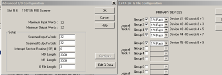
The data mapping of the 1305 drives is straightforward in that project. They use the smallest "1/4 rack" RIO memory allocation.

This is shown in the "G-File" configuration for the 1747-SN module, and confirmed by the labels for the control and speed reference words.

You would have to examine the DIP switches on the 1203-GD1 modules to be absolutely certain which drive has which RIO address number. The names assigned in the program are just "Drive 1-5".

The 1747-SN is in Slot 6:

I:6.0 Drive 1 Status Bits
I:6.1 Drive 1 Feedback Word
I:6.2 Drive 2 Status Bits
I:6.3 Drive 2 Feedback Word
I:6.4 Drive 3 Status Bits
I:6.5 Drive 3 Feedback Word
I:6.6 Drive 4 Status Bits
I:6.7 Drive 4 Feedback Word
I:6.8 Drive 5 Status Bits
I:6.9 Drive 5 Feedback Word

O:6.0 Drive 1 Command Bits
O:6.1 Drive 1 Reference Word
O:6.2 Drive 2 Command Bits
O:6.3 Drive 2 Reference Word
O:6.4 Drive 3 Command Bits
O:6.5 Drive 3 Reference Word
O:6.6 Drive 4 Command Bits
O:6.7 Drive 4 Reference Word
O:6.8 Drive 5 Command Bits
O:6.9 Drive 5 Reference Word

In RSLogix 500, you can configure the bit number displays to show Word/Bit or to show the absolute Bit offset. In the copy of the program that was posted, the Bit offset method is used, which I find less useful for this purpose.

Example:
O:6/69 = O:6.4/5 = Drive 3 Reverse

I find it much easier to think of Word 4, Bit 5 = Reverse because Bit 5 is the Reverse bit for every drive.

To change that display option globally in RSLogix 500, go to View -> Properties -> Address Display and change the radio button for the I/O Bit Display mode to "Slot.Word/Bit"

G_File.PNG
 
Some other comments based on a very quick review:

In the SLC-500 platform, only LAD2 executes automatically and by default, similar to Siemens OB1 or ControlLogix Main Program of the Continuous Task.

Most programs that use multiple subroutines use LAD2 to execute them in sequence with Jump to Subroutine (JSR) instructions.

This program doesn't follow that convention and you have to look a little deeper.

LAD2 does execute JSR jump to subroutine instructions, but only to LAD 11 and LAD12, based on the state of an unlabeled internal bit, B3:6/5.

My guess is that B3:6/5 was turned = 0 when the machine was commissioned, then never changed. Similarly, the execution of the drive control subroutines depends on B3:6/4 = 1.

LAD12 is labeled OPERATION, so it makes sense that it actually contains most of the operational code.

LAD12 does the conventional calling of subroutines at the end, calling the Drive 1-5 control subroutines 13,14,15,16,17, 18.

My quick reading of the program is that LAD 3,4,5,6,7,8,9,10 are probably an "alternate" or "manual/testing" control program.

They are all called by LAD11, which is only executed if B3:6/5 = 1, and appear to control most of the same I/O as the ordinary program.
 
https://www.spectrumcontrols.com/products/universal-gateway/

If all you are doing is PLC to PF then the Spectrum Controls Gateway should be able to handle the job. There are a couple of things worth noting. One is the Gateway is configured using a web browser so you don't need to load configuration software. More importantly, the Gateway does all of the communications I.E. you don't have to have any message instructions in the PLC. For control you will simply create a tag map where the 5/04 is the source and the PF is the destination. For more details you can check out the webinar video on the product page and skip ahead to 6:50 to get to the part that shows how it basically operates and then how to configure it (the basic configuration needed to communicate between two devices).

One of the original intents of the Gateway was to provide a means of upgrading a system over time without having to do a lot of reprogramming an existing PLC network so it is in line with what you were trying to do.
 

Similar Topics

I have something preventing me from sending an email from a 5/03 to a Net-Eni to the email address. I'm not sure if the problem is in my MSG...
Replies
0
Views
4,803
Can someone tell me the part number of the rs232 cable I need? Would any of the after market programming cables work?
Replies
1
Views
1,632
Howdy. So I am trying to create a small network of just 2 SLC 5/03's and my programming laptop. The SLCs are connected via RS232 to some...
Replies
3
Views
1,870
I have a 5/04 connect to 1761-ENET. I have a controllogix chassis with 1756-EN2T and 1756-DHRIO. Is there a way I can MSG a 5/04 through the...
Replies
4
Views
1,762
I've been racking my brain and trying everything that i could think of but now i think i might be doing the imposible. lol What I'm attempting to...
Replies
4
Views
3,392
Back
Top Bottom