Inspection Stations using BSL/BSR

jri4au

Member
Join Date
Feb 2016
Location
Clanton, AL
Posts
13
I am having difficulty understanding how to write this station. I have run into conflicting information and am looking for some ideas. The camera is sending a pass and job complete, I need to reject it at some point downstream. The sample I was given is not helping
job -------------job----- one --------------- index
---||-------------||--------[]-------------------()
complete-------pass-----shot----|------------bit
----------------------------------BSL

What is the one shot doing here, or the index bit? If I am right, job pass writes a 1 to the shift register, when it doesn't a zero is entered. Each cycle it shifts until you get ready to UL. Can I use the zero in the UL to kick the fail? Writing it this way how does the processor know to write the 0 to the register. Hopefully you guys see the gap in my training and can help. Thanks
 
Last edited:
Most Bit Shifts have a place for the input bit address and the output bit address. The one shot is probably so the bit is not forced on when the register shifts.
 
if the job complete bit and the job pass bit are both 1 it will turn on a one shot bit which turns on the index bit for one scan only.

when the logic in front of bit shift instruction goes true,
the bit shifts the information.

at your kick station you look at that bit and say if the bit is off, kick out the part.

Sorry, I don't understand what UL means.

james
 
James, Thank you.
UL is unload
I understand better how the one is entered.
If I understand what you are saying the only time the bit shifts is if it is true? That being the case, how will the kicker ever see a 0?
Do I compare complete and pass if both true write a 1 and then if complete but not pass write a 0?
 
Last edited:
Jax, Thank you. Unfortunately my problem is identifying the correct order. I have watched several videos demonstrating what appears to be contradictory logic. I would screen shot but my activation expired and I can't open the file until Thursday. Until then I am writing it out in a notepad to translate in. Trying to get ahead of the project. I will have a week to installation after we get samples for the camera and they are installing printers this weekend.
 
Last edited:
Garry, Thank you. We are basing our camera trigger on print complete. I will have to ask if an encoder signal is available. With your link to AD having a simulator I can probably hammer out the differences between Do-more Rs 500 (the project in mind) and 5000. This will help. I am not all the way there but you guys are getting me there.
 
Last edited:
I assume you are using a Cognex system. I've done one based on Profinet (no hardwired I/O for the vision system) but everything coming to the PLC over the network.
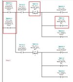
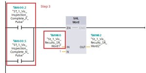
I have attached a few images, Step 1, Step 2, Step 3, Step 4.
Step 1: You have to monitor for the vision system "complete", this is tricky with Cognex as it "toggles" per each inspection (0---->1 ---->0 ---->1).
You haver to capture each transition and act upon.
Step 2: as you can see, upon a transition, you mark the bit(s) based upon inspection results ("Good Product" bit as well as "Mark_SR_bit").
A "pass" will mark the good product bit as well as the SR bit with a "1".
In case the result is a fail or the inspection results are not valid the SR bit will be "0", therefore you process the results later on and reject anything marked with "0" (based on SR bit status).

Step 3: Stuff the current vision results to a shift Register.
Step 4: Process everything on your station based on Shift register bit status.
The IMPORTANT thing to remember is that you capture results, mark and shift at the same pulse (ons).
The placement of the logic is also important as you can see from the step numbering.
If you decide to alter it you may end up with unwanted results.
I am using Siemens but you can look at the logic and adopt to RS500 as it is ladder after all.
Hope this helps.

Step_2.jpg Step_3.jpg Step_4.jpg
 

Similar Topics

Good morning guys, I'm searching to find a product that can inspect the width and depth of a keyway on the end of shaft. Width is 1/4" ±.001...
Replies
0
Views
286
Hi All, I'm doing mainly PLC programming but dabbling in industrial networking. I am investigating an intermittent communication fault between a...
Replies
4
Views
1,703
Hello, I have been shopping around for a while, seems like alot of them will only inspect a small area. What I want to do is inspect a loading...
Replies
7
Views
1,882
Hi Group My control box uses 110VAC incoming from customer supply. It has a PLC and a DC power supply both running on 110. The PLC draws 0.8...
Replies
1
Views
1,690
Could someone suggest any instrumentation to internally view non conductive material? Example : Validate a centered wick in a candle internally...
Replies
3
Views
1,474
Back
Top Bottom