PLC value different from Flow Meter

goodoboy

Member
Join Date
Aug 2010
Location
Houston
Posts
86
Hello,

Why do I have two different readings between transmitter and PLC

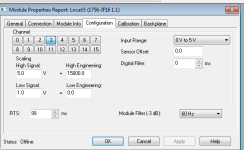
We have a flow meter sending 4-20 HART to PLC AI card attached with configuration shown in attachment.

The meter display is showing about 900 scfm, but the online live PLC value is showing about 1600 scfm.

Configuration is with a 250 ohm resistor on the AI inputs terminal block.

The loop current matches the PLC value not the meter display.

Is it possible the PLC AI card is not setup for 4-20mA HART?

When I send a 4-20mA only signal to the PLC, PLC matches.

Thank you
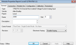
Screenshot_16.png Screenshot_17.png
 
Check how the flow transmitter is set up.
Does it match how you have set up your analog input card. ( 0-15000)

4ma = ??
20ma = ??
 
Configuration is with a 250 ohm resistor on the AI inputs terminal block.
I suppose you use an external resistor to convert current to voltage. In the manual, page 60:

http://literature.rockwellautomation.com/idc/groups/literature/documents/um/1756-um009_-en-p.pdf

you can see that each analog channel has a 249 ohms resistor. Usually, you need to put a jumper between RTN and iRTN-x (where x is the channel number) to get the channel working. If you are doing that and adding an external resistor, you'll get a different reading. Take a decision: use the internal resistor or the external one.

As @AGill wrote, set the channel to current.
 
Why do you have 0-5V selected on the input card config? Why not just use 4-20mA?

Thank you AGill,

I do not understand why this is showing 0-5V as input. A PLC contractor sold this to us this way. All the channels are setup this way.

When we unhooked the transmitter and send a 4-20mA value to PLC AI card channel, we see the correct corresponding flow value that match that mA sent.

I am at home now, is it possible to set the card input to 4-20mA. I am not sure that is an option.
 
I suppose you use an external resistor to convert current to voltage. In the manual, page 60:

http://literature.rockwellautomation.com/idc/groups/literature/documents/um/1756-um009_-en-p.pdf

you can see that each analog channel has a 249 ohms resistor. Usually, you need to put a jumper between RTN and iRTN-x (where x is the channel number) to get the channel working. If you are doing that and adding an external resistor, you'll get a different reading. Take a decision: use the internal resistor or the external one.

As @AGill wrote, set the channel to current.

Thank you,

I am confused after looking at page 60.

Why do we have an external 250 ohm resistor for our 4-20mA input signals? If the AI card already have an internal 250 ohm resistor.
 
Thanks,
Will the PLC AI card read 4-20mA HART as well or just 4-20mA?

I think the transmitter is setup to output 4-20mA HART and the HART (digital) causing incorrect readings on the PLC AI channel.

"HART" will not cause an incorrect reading. If the card is not a "HART" card the "HART" portion of the signal will be ignored. It has no effect on the 4-20ma.
 
1.
I do not understand why this is showing 0-5V as input.

AI_card_setup.png


The flow meter's 4-20mA is converted to a 1.0 to 5.0 Vdc signal by the IR drop created when the current goes through the external 250 ohm resistor mounted on the terminal blocks.

That voltage is then fed to each of the AI cards.

The setup is correct. I suspect that the choice of input ranges on the AI card is 0-5Vdc, and that there is not a 1-5Vdc option.

The scaling, Low Signal 1.0V = 0.0 Eng units and High Signal 5.0V = 15000 eng units, is correct because the useable range of this signal is 1-5Vdc.

This is a perfectly legitimate way to split a current signal, by making the current signal into a voltage and using the voltage signals.

The AI cards in this case DO NOT SEE a current signal, they 'see' a voltage signal, so the use of another current dropping resistor will only create a problem, not solve a problem.

2.
A PLC contractor sold this to us this way. All the channels are setup this way.

As far as I can tell, the contractor did it right. Leave well enough alone.

3)
I am at home now, is it possible to set the card input to 4-20mA. I am not sure that is an option
It is not an option. If you change the configuration for current inputs, then you will need to change the field wiring to match, which means re-wiring the current signal in series through the two AI's.

Given that you do not understand Ohms Law, the difference between current and voltage signals, or series/parallel splitting, you're best advised to leave well enough alone.


4) The commment made about voltages "always being flakey" is not true.

AI inputs are ALWAYS voltage inputs.

Signals that are not voltage signals have to be made into voltage signals to be 'read'. That's the reason for the dropping resistor that's required for current inputs - the resistor converts the current to a voltage signal that the AI can use.

Sometimes that dropping resistor is internal, sometimes it is external (like in this case).
 
1.

AI_card_setup.png


The flow meter's 4-20mA is converted to a 1.0 to 5.0 Vdc signal by the IR drop created when the current goes through the external 250 ohm resistor mounted on the terminal blocks.

That voltage is then fed to each of the AI cards.

The setup is correct. I suspect that the choice of input ranges on the AI card is 0-5Vdc, and that there is not a 1-5Vdc option.

The scaling, Low Signal 1.0V = 0.0 Eng units and High Signal 5.0V = 15000 eng units, is correct because the useable range of this signal is 1-5Vdc.

This is a perfectly legitimate way to split a current signal, by making the current signal into a voltage and using the voltage signals.

The AI cards in this case DO NOT SEE a current signal, they 'see' a voltage signal, so the use of another current dropping resistor will only create a problem, not solve a problem.

2.

As far as I can tell, the contractor did it right. Leave well enough alone.

3) It is not an option. If you change the configuration for current inputs, then you will need to change the field wiring to match, which means re-wiring the current signal in series through the two AI's.

Given that you do not understand Ohms Law, the difference between current and voltage signals, or series/parallel splitting, you're best advised to leave well enough alone.


4) The commment made about voltages "always being flakey" is not true.

AI inputs are ALWAYS voltage inputs.

Signals that are not voltage signals have to be made into voltage signals to be 'read'. That's the reason for the dropping resistor that's required for current inputs - the resistor converts the current to a voltage signal that the AI can use.

Sometimes that dropping resistor is internal, sometimes it is external (like in this case).

Thank you for the detail response. This really help me . Thank you.

We still have the issue and I believe the problem is with the flow meter sending the wrong 4 -20mA then what is shown on the meter display. Maybe the Digital to Anolog converter in the meter is bad.
 
Maybe you need to check the internal setup of the flowmeter using a HART communicator. You can execute a loop test as well (forcing 0-25-50-75-100% of the range).
 

Similar Topics

I want to set user security level based on the value of a tag in my PLC called "ActiveUser". That tag will contain the A-P code which we use for...
Replies
6
Views
214
Hello You guys helped me with a similar issue some time back on storing totalized values to different tags each month. I have a similar issue...
Replies
19
Views
1,495
Hello everyone, been trying to figure this one out for awhile now. The system configuration is as follows: Processor is an L63 5563 ControlLogix...
Replies
0
Views
611
Hi; We installed an orifice plate type steam flow transmitter which configured to give 4-20mA signal correspond to 0-9ton. I given that signal...
Replies
24
Views
5,611
I have a Horner PLC that is reading Ascii string from a device. When the device responds, it responds with the hex value in Ascii. I need to...
Replies
8
Views
2,381
Back
Top Bottom