PLC Totalizer and Storing each Value

Ones_Zeros

Member
Join Date
Feb 2014
Location
at work
Posts
367
Hello
You guys helped me with a similar issue some time back on storing totalized values to different tags each month.

I have a similar issue that I cant figure out and also a totalize issue that I was hoping you could assist me with.

What I have is a flow meter that measures water flow. I have this tag feeding the input to a PLC totalizer function with two outputs current day total and previous day total.

1. I have a totalizer setup to total the water each day. It isnt totaling correctly. The data is not close to what is recorded on the totalizer instrument. What could I check to see why the totalizer is not accurate?

2. I also need to setup a second totalizer to record the water data from each truck, dump this data into a tag array (for example T1, T2, T3, T4...etc), then reset the total to prepare for the second, third, trucks. I may get 20 trucks a day.
So my tags would have water data for all 20 trucks that flowed through the meter. Once i get the totalizer accuracy corrected then I need to figure out how to setup storing the data.

i appreciate the help
Thanks
 
Broad question yields a broad answer.

PLC totalizers suffer from rounding errors and the limitation of the 32-bit float to hold enough significant figures.

I've typically gotten around those limitation by totalizing a small number (sum of the flow in the last xx msec) in one Real register, and then when that number gets too big (like greater than 1), I subtract that value from my small totalizer and add it to my big totalizer.

If a Real can hold roughly 8 sig figs, then my small totalizer is handling 0.0000000 values of flow, while my big totalizer can accurately count 00,000,000 values of flow.

As for your truck problem, that's a matter of data handling, probably using indirect addressing references to an array of totals. But you need to figure out what your start/stop events are, how to know when it's time to point to a new register because its a new truck (and not the same truck that simply took a break in pumping).
 
As for the truck totalisers just use a shift register so on a signal to detect the truck empty (or fill) just put the current total in var[0] & shift the data, so in effect if you have an array of 21 vars, then each time you move the new truck total into var[0] & shift it moves the totals down.
display the variables 1 to 21 on the HMI or scada etc.
 
1. What is you PLC scan time?
What is your flow pulse time?


Usually this isn't problem, but PLC scan time should be at least 2-3 times faster than pulse time for that every pulse is counted.
 
1. I have a totalizer setup to total the water each day. It isnt totaling correctly. The data is not close to what is recorded on the totalizer instrument. What could I check to see why the totalizer is not accurate?
What are you comparing it against? What's the precision and calibration of the device used to check this measurement?
How does the measurement look like during the day? That is, do you see the dosed quantity increase smoothly, or do you see spikes in total that don't match the movement of the plant?

Does the instrument have its own totalisers? What is it saying? How are you accumulating the flow? Pulse? Analog?

2. I also need to setup a second totalizer to record the water data from each truck, dump this data into a tag array (for example T1, T2, T3, T4...etc), then reset the total to prepare for the second, third, trucks. I may get 20 trucks a day.
So my tags would have water data for all 20 trucks that flowed through the meter. Once i get the totalizer accuracy corrected then I need to figure out how to setup storing the data.

An array would be my bet here.
 
Is this the function (instruction) you are using? I.e. is the flow meter providing a flow rate value (units of volume per time e.g. gills per fortnight) to the PLC, and that instruction is integrating* that sampled value over some time interval?

* multiplying the rate value by the time interval and summing each product?

We will need more details to assess why the data are "not close." What are typical flow rates and data intervals, what are the data types of the various parameters passed to the totalizer function, can you show your code, etc.?
 
Last edited:
I have used the totalizer instruction on AB compact and control logix (the OP did not mention any PLC brand). I was trying to compare data from instrument to totalizer instruction data, the values were almost the same, I had Hart modules in both cases
(compact and control logix).
The important thing is to use the same time interval and mass or volume units.
Please follow Drbitboy´s recommendations.
 
Hey Guys I'll try to answer all the questions
I appreciate the help and feedback

1. The PLC is a Compact Logix L32E
2. The Flow meter is a Coriolis 5700 meter
3. The units are in bbls/min coming into the PLC
4. I have another totalizer setup from an previous flow meter installed and it totalizes fine. I thought it might be the settings in the TOT, but I used the same exact settings. the previous flow meter units is in gal/min though.
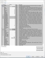
5. I have the "Timebase" setting to 3 in the TOT settings. See pics
6. The 5700 meter does have its own totalizer built in and it is correct. I assume its a setting in the PLC TOT.

thanks for helping

TOT_02.JPG TOT_03.JPG
 
Last edited:
As this is totalisizing from analog input and not from pulse you should check accuracy of analog input.
Which are raw data values on 4mA and 20mA if you simulate them from meter?
 
I notice that TOT2 has a negative flow rate and it seems that the totalizer is running. This may make your total count backwards.

TOT3's flow rate is roughly zero, so it isn't changing.

Presumably these shots were of times when neither system is really running and is there just to show us what your settings are. But if TOT2 is "flowing backwards", that could possibly be why it disagrees with the correct value.

This is just a SWAG -- you get what you pay for and you haven't given us very much to go on.

Another SWAG: are the totalizers in different Tasks with different update times ? Totalizing is all about rate * time, and if the time interval is wrong, the total will be wrong.
 
Last edited:
...
3. The units are in bbls/min coming into the PLC
...

5. I have the "Timebase" setting to 3 in the TOT settings. See pics


3. "bbl/min" says the time units of the value feeding the TOT instruction (i.e. the In pin) are minutes. bbl/min is an odd unit, Bbl/d (per day) is far more common, IIRC, but this says the time unit is minutes.

5. says the units of the value feeding the TOT instruction are days.

You did not describe the magnitude of the difference between the PLC TOTalizer result and the flow meter totalizer. If it's a factor of 1440* (or 1/1440*), then changing Timebase to 1 (time units of the value feeding the TOT instruction are minutes) might be the fix you are looking for.

* N.B. 1440 minutes = 1 day
 
Last edited:
Could someone explain to me how the flow (TOT_02, TOT_03 "The analog signal input to the instruction") can be negative?
 

Similar Topics

I have an existing system that is measuring and totaling the flow of 6 different flow meters. They are all reading high and have no idea why. This...
Replies
35
Views
3,783
Hi; We installed an orifice plate type steam flow transmitter which configured to give 4-20mA signal correspond to 0-9ton. I given that signal...
Replies
24
Views
5,615
Hi All, I am currently working on a project of which we have used s7-300 PLC, and I am new to it. I need to provide a totalizer logic using...
Replies
1
Views
3,805
Well, I have been searching and trying for days and not come to an accurate solution on this simple but complicated peice of programming... I...
Replies
5
Views
5,693
Hi guys, We've a client that need to monitor the totalizer signal in the PLC (HMI). According to the client, the output is frequency/pulse. Does...
Replies
3
Views
2,206
Back
Top Bottom