Ab 1771 Btw Help Needed

dbcooper41

Member
Join Date
Oct 2004
Location
raleigh, nc
Posts
9
hello,
we have a piece of equip controlled by an allen bradley plc 5/20.
after a recent power outage it has failed to resume normal operation.
an analog input card 1771-IFE/C has a blinking green light. the t-shooting guides says this indicates it is waiting on a "BTW", block transfer write.
can anyone suggest if this is a fault with the i/o card, the processor, or a software glitch. recently the original programmer came in and made a change which involved this particular I/O board. unfortunately he is out of the country and unavailable.
is there a way completely reset the system? i've tried a power down, board removal without any success.
thanks for any help you can give.
david
 
this sounds SO familiar ...

Greetings David,

the material below is from a recent post ... see if it fits your problem ... since you haven’t told us where (rack – group – module) your particular module is located, I’ve replaced that specific information with “XXX” and “Y” and “Z” in the first paragraph below ...

suggested plan of attack: do a “Find All” search for BTW and track down the Block Transfer Write instruction which is assigned to this module ... you’ll know that you have the correct rung when you find a BTW addressed as “Rack XXX” ... “Group Y” ... “Module Z” ... when you find it, take a good look at the “Enable Bit” and the “Done Bit” and the “Error Bit” indicator flags on the right side of the BTW instruction ...

depending on how the original programmer set up the BTW rung, the bits should be in either one of the two following conditions:

1. the Enable flag should be OFF, the Done flag should be ON, and the Error flag should be OFF ...

... OR ...

2. the Enable flag and the Done flag should both be toggling ON and OFF rapidly ... the Error flag should be OFF ...

regardless of what state the flags are in, I’d go ahead and re-trigger the BTW rung to execute again if I were you ... that’s assuming (gosh I hate that word) that there are !NO! safety issues to worry about with your application ...

basic idea: whenever the IFE module is powered down, it loses its configuration ... in other words, it’s sort of like a computer without an operating system ... specifically, it’s a mindless idiot ... the configuration is stored in approximately 20 to 39 words of your processor’s memory ... usually in an integer file ... you can find the address as the “Data File” entry on the BTW instruction ... the Block Transfer Write instruction is something like a mailman ... when the BTW executes, the mailman picks up the configuration data from the “Data File” address and delivers the data out to the module’s Rack/Group/Slot address ... the IFE module receives the configuration data and becomes intelligent ... now it’s ready to send you meaningful data every time a BTR (Block Transfer Read) mailman executes ... this separate BTR is the mechanism that carries the channel data from the IFE module to the PLC processor ...

the big thing is that if the IFE module doesn’t get the correct configuration, then the data that it gives to the processor is erratic and basically meaningless ... and it can definitely jump around all over the place ... does this sound familiar? ...

my best guess ... your IFE card was powered down and (for some reason) the BTW responsible for the module’s “configuration” did not get executed properly ... most common reasons for the BTW to not execute are the rung got scrambled by a fat-fingered programmer ... or the BTW rung is not being scanned by the processor ... this may be caused by a JSR (Jump to Subroutine) rung being messed up ... or other things along those same lines ... if it seems like I’m on the right track here, then post again and we’ll continue troubleshooting ...

no offense intended ... do you know about Block Transfers? ... how about setting up the configuration for the IFE? ... we can probably help but we need to know where we’re starting from ... and what’s your deadline here? ... note that “As Soon As Possible” is not a valid answer ...

and finally ... welcome to the forum ...

PS edit: unless you have some specific reason not to, it would probably be a good idea to zip your .RSP file and post it here ... it will probably save us a lot of time ... here's a "how to" just in case you need it ...

how to post a program file
 
Last edited:
I wonder if the values in the data table for the BTW zero'ed out when the power kill happened. I've seen processors dump data table values before and then you lose all of your formatting for Analog inputs and outputs.
 
I had a similar situation about 3 weeks ago, cause was a MAJOR electrical storm. Had two cards out right fail, and one with the blinking light. In my case the cause was a bad card.

Have you tried using a different I/O card, if you don't have a spare,
but have another identical card in the Rack, try swapping it into this cards position, and see what happens.

Ken
 
look out for the "gotcha" jumpers ...

David,

Ken has a good idea ... but ...

just remember there are little jumpers hidden inside those IFE cards ... so when (if) you swap a couple of modules, be SURE that the jumper positions match ... or you could be comparing apples to oranges ... the jumpers select things like current vs. voltage inputs ... and single-ended vs. differential wiring ...
 
thanks for the suggestions. i don;t have a spare input card but there is another in the system. i'm gonna try swapping them this afternoon and hope that solves the problem.
if not i'll zip up the program and post it.
can anyone suggest a source for reasonably(yeah right) priced AB parts and software?
i've convinced the powers that be to purchase a copy of rslogix but the local dist quotes $3,500. in another thread i read references to the software in the $1,100 range.
thanks for the help.
 
can anyone suggest a source for reasonably(yeah right) priced AB parts and software?

Try E-Bay
 
well ... since you’re using the PLC-5 system, you’ll need RSLogix5 software ... and the last time I checked, about $3,500 was the going rate ...

the RSLogix500 software for the smaller SLC-500 and MicroLogix systems usually runs for around $1,100 ... maybe that’s what you’re thinking about ... don’t buy that one ... it will NOT work with your PLC-5 system ...

and incidentally ... you didn’t answer any of my questions from before ... not that I’m sensitive or anything like that ... it’s just that it’s a lot easier to help when we know more about the situation ...
 
ron,
not sure if my last post made it so i'll risk repeating myself.
this is my first experience with the btr/btw configurations. i feel like i have a general understanding of what's going on. but as they say, "the devil's in the details".
after swapping input cards i now have 2 with blinking green lights. it appears to me the processor haas stopped processing for whatever reason. i can manually command some output from the front panel but it doesn't seem to be reading any inputs from the boards in question.
is there any trick to forcing the processor to restart from the beginning?
can i possibly change the chassis config setting to reload from eeprom after a power outage using switches 6 and 7?
the boards i'm having trouble with are module 6 in slot 5 and module 7 in slot 6.
i'm attaching the program as a zip file.
i have a feeling i'm stuck without rslogix5.
thanks, this forum is excellent.
 
just remember there are little jumpers hidden inside those IFE cards ... so when (if) you swap a couple of modules, be SURE that the jumper positions match ... or you could be comparing apples to oranges ... the jumpers select things like current vs. voltage inputs ... and single-ended vs. differential wiring ...

If you try my experiment with the swing arm off, it will not matter.
You're only concern is, does the blinking light go away. If it does
but the swapped card back where it came from. Buy a replacement for the defective one and then ensure that the settings are the same.

I have bought a lot of used/refurbed AB stuff from www.plccenter.com

If you call the phone number listed on the website, they will quote new AB stuff also, don't know about software though.


Ken
 
David,

I can open and read your file ... but here’s a major concern ... if you don’t have RSLogix5, then where did you get this file? ... I’m guessing that it’s a “spare disk” copy ... specifically, it’s not guaranteed to be the same one that’s currently running in your processor ... so ... if the engineer worked on your system recently, there’s a chance that some change that he made might not show up in the program file which you’ve posted ...

anyway ...

there is nothing really obviously wrong with the IFE card setups as shown in your program ... all of the configuration data looks normal based on what I can see from this end ... but once again, I’m HIGHLY suspicious that the program that you’ve posted might not be EXACTLY the same as the one in your processor ... the processor’s time stamp was set for 1997 when this program was saved ... true, the PLC’s clock is not always set correctly ... but it does make me wonder just how old this copy is ...

you said:
recently the original programmer came in and made a change which involved this particular I/O board.

is the program you posted a recent “save” made AFTER the change? ... or maybe an older copy made BEFORE the change? ... the file’s date stamp in the zip file says 1998 ... I've got a BAD feeling about that ...

one tiny concern is: you have 11 BT Writes and 11 BT Reads ... that in itself is ok ... but they’re ALL set for continuous mode ... I’ve never seen that many BT’s run in continuous mode before ... I’m just a little bit suspicious that maybe all of that “continuous” communications traffic MIGHT be causing a hang up ... admittedly I’m grasping at straws here ...

you said that you tried a system power down to “reset” the system ... as long as there are no safety concerns, I’d suggest that you try it again ... and be sure to leave the power off for at least 10 or 15 seconds ... sometimes a quick toggling of the power switch won’t do the trick ...

you asked about trying to download from the EEPROM ... what makes you think that you have an EEPROM? ... if you have one, it should be sticking out of that little metal hinged “secret compartment” door right on the FRONT of the processor ... I’m betting that you don’t have one on this system ... let me know if you do ... even so ... if the programmer didn’t burn a copy of the LATEST program onto the EEPROM, then you’re probably not going to solve anything by downloading ...

next ... you STILL haven’t told me what your deadline is on this project ... if it’s anything pushing, then I’d recommend that you call in reinforcements ... how far away is your Allen-Bradley distributor? ... sometimes they have a technician available that might be able to help you out ...

sad news ... if you don’t have a copy of the software, I’m afraid that we’ve hit the end of the line ... there’s just not much you can do without going online and getting “inside” the processor ...

good luck ... and PLEASE come back and let us know what the final outcome turns out to be ... wish I could be more help ...
 
Last edited:
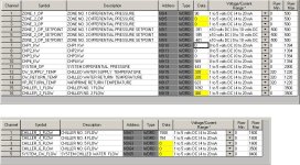
and just before I go home for tonight ... here’s a quick (partial) screen shot of the configuration screens for your two IFE modules ... maybe you can spot something suspicious here ... but again ... even if you DO see something fishy, you won’t be able to do anything about it without the software ...

iosetup.jpg
 
ron,
you are exactly right about the file. my apologies. that was an old copy from before the recent changes. i'm attaching the new file which strangely says created in 2004 and modified in 1998. not sure how that came about but it is the copy left by the engineer on august 27. the changes he made involved raising the max values for the chiller flows and removing/disabling control for chiller 5 flow valve.
we have the pumps and valves in manual now so i have several days to work on this fortunately.
we're purchasing RSlogix5 so i'll be able to reload the program when we receive it.
when i swapped input boards the system was powered down long enough to reconfigure jumpers on both boards, about 5 minutes, so i assume that would have reset the processor.
we don;t have an eeprom installed, now that i know where to look for one. (i've obviously got minimal documentation on this equipment).
thanks for the screen shots. i'm using them as my first lesson in using rslogix.
thanks for all your help.
david
 
David:

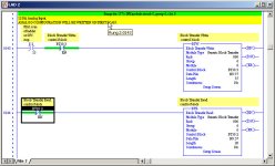
When the rack containing the 1771-IFE analog input module is powered down and up, the run light of the 1771-IFE starts blinking. This indicates it is waiting for CONFIGURATION BLOCK TRANSFER WRITE. (See the manual on page 7-3. You can get it from Online Manual on AB website.

If you look into the PLC 5 Instruction Set Manual on page 15-10 it describes Continuous operation. It mentions something about Continuous Operation continuing as long as processor stays in run mode. It sounds like the Analog input cards are waiting for the configuration to be written to them.

I can't say for sure that this will fix it but it may be worth a try. Try changing your logic from Continuous operation to Not continuous.

Here is an example using 1 of you analog input cards.

Kim

btr.jpg
 
Last edited:
wait a minute ... I've seen this program before ...

Greetings David,

oops! ... the file that you just posted (in your post #13) is exactly the same as the first one (from your post #9) ... same date ... same time ... same program ...

you said:

we're purchasing RSlogix5 so i'll be able to reload the program when we receive it.

be careful there ... based on what I’m seeing from my limited perspective, I’d say that it’s quite possible that the programs you have available (on disk) might not be the “latest and greatest” versions ... basic idea: you could conceivably wipe out the engineer’s latest changes by overwriting them with an old version of the program file ... that would be an “ungood” situation ...

then again ... MAYBE the older version (without his latest changes) would work better than the most recent ...

also ... you’re going to need a programming cable in addition to the software ... post again and ask questions if you need to ... since you are lucky enough to have a PLC-5/20 processor (an “enhanced” model) you can actually build your own cable from Radio Shack parts in a pinch ... the “official” cable from Allen-Bradley is part number 1784-CP10 ... the communication “driver” that you’ll need in RSLinx will be the “RS-232/DF1” driver ... be sure to press the “auto configure” button to make the setup as easy as possible ... and PLEASE tell me that there is NOTHING currently plugged into the 25-pin connector (channel 0) on the front of the processor ...

note to Kim ... thanks for trying to help ... I’m sure that David appreciates it ... the BIG problem is that David does NOT have the RSLogix5 software available ... yet ... so the amount of troubleshooting and corrective actions that he can take are extremely limited ...

David, I’d still suggest that you consider calling in reinforcements ... this is going to be a “tough-row-to-hoe” for a first time experience with RSLogix ... we’ll help as much as we can ... but I certainly wouldn’t recommend this as a “first-time-out-of-the-box” learning experience ... it’s good to know that you at least have some slack in the deadline department ...
 

Similar Topics

So, I have a 1771-IFE set up for 16 single-ended analog inputs. Currently only 7 of them are being used. We need to add 5 more inputs. This is...
Replies
17
Views
5,745
Hello, I am having issues getting my channel output voltages to change (1-5vdc) by manipulating the data file values. I am also curious as to my...
Replies
5
Views
1,873
Hi, Been a long time since I have been on here. I have a 1771-IFM Fast Millivolt card that I just can't seem to get to work. I am having a...
Replies
17
Views
5,219
This one has me climbing the walls right now... Should have been simple, toss a SDN scanner into the PLC rack, configure it up with RSNetworx...
Replies
4
Views
2,905
Preface: Kinda long, so I made section titles Intro: I just want to see if anyone here has seen anything similar. A PLC5-40 series C enhanced...
Replies
3
Views
365
Back
Top Bottom