A cooling system problem

georgeawny

Member
Join Date
Sep 2011
Location
Helwan, Cairo
Posts
10
Hello,
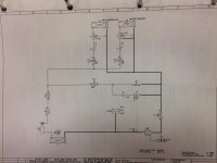
hope you're doing well, i've a cooling system diagram which i can't understand it -see the attached photo-.

Can anybody help me to figure out the function of the following valves:
Y11 : Re-injection
Y13 : condensate protection
also what do these symbol's function: 2, 3, 4, 5, 7, 9, 10 and 11

Another thing in general, when i need to apply PID controller to this system, which element should i control?!! Is it the compressor?! or the direct cooling valve (Y14).

Any help will be appreciated.🤞🏻
Thanks.

ref.jpg
 
From what I can see.

Your y11 valve is a recirculate valve so when system is regulating it is keeping flow and not freezing up.
Looks like 2 of same systems y13 and y14 are shutoff for loops, the valve on top of them is what would be PID controlled, since it is marked with TC and has the feedback going into it.
Good luck hope I'm correct and it helps.

Cowboy
 
It looks to me that you will be best served by hiring someone with HVAC expierence and learn from them.
Your questions suggest that you need a little more help than is practical in a forum.
 
+1 for reply #3.

For PID control, someone will need to define the controlled variable, probably something on the load side of the evaporators, which will help determine the manipulated variable/control element.

My interpretation is that "5" and "7" are expansion valves, and "Y13" and "Y14" are refrigerant valves. If Y13 is "condensate protection," maybe there is some kind of shutoff control (not shown) in case condensate is detected on the compressor input.

Valve 11 might have something to do with suction control. It is marked "PC" but with no feedback shown.

Your best option may be going back to the original supplier of the system, though I realize that is not always possible.
 
Last edited:
2 is buffer for liquid
3 is filter drier
4 is looking glass
5 is one way valve
TC is a thermostatic expansion Valve, it will control
Y11 and the valve 10 is to prevent overheating of compressor it will give a bit liquid in the suction line to cool down these.
11 is a pressurecontrolvalve, to avoid freezing up of the coolers.
9 is not really needed, however has same function as 10.

control can be done on Y14, simple with a thermostat.
The compressor should start when Y14 is open and stop when suction pressure is LOW.
I do not know what defrost safety is doing.
Thanks Shooter for your helpful reply, i'm new to cooling systems and this is a refrigeration machine i'm gonna control using PLC (PID control). i've read about cooling systems but i need your help a little bit.

- about Y11 you told me that i should open it to prevent compressor over heating, so how could i know that the compressor is overheated ?!! i only have one RTD inside the room.

- about Y13 (condensate protection), when should i open it?!! and what's its function ?!!

- the last thing in PID control, can i control the Y14 valve using a PWM from PLC?!! if that is right, you told me that the compressor should work with this valve (Y14) so, wasn't it get damaged when it get on/off in a high frequency like the valve?!!!

I'm sorry if i've many questions, i hope that you could help me.
Thanks a lot for your support.
 
Just going back to the drawing, would there not have been an index to the drawing and or goggle for what the drawing shows as a symbol.
But as been suggested you should have a basic understanding of how a refrig/freezer system works as Russ suggested, BEFORE you go and put a PLC to it for control.
BUT the question to you georgeawny, is why is a PLC needed (let alone how you are going to code it, when you seem to be struggling with what it even is), it seems a basic control system like controlling a fridge/freezer, does your home one, have a PLC controlling it, let alone a PID control( NO, as suggested just a thermostat).

Thanks PLCnovice61 for your reply,
this machine is a laboratory machine in a factory for Fire Fighting Extinguisher where i'm working, not in my home. this machine has a room, we use to heat it sometimes and put it at 0 degree the other time to simulate aging (as days and months pass).

its control card is damaged and I'm trying to make a new control system for it using PLC SIEMENS S7-1200 (PID control). that's all

i've read about refrigeration system works. and i searched google for the symbols but i found nothing, so, I'm posting here if someone could help me to understand how this cooling system works.
 
On all expansion valves is a sensor attached (wired or direct) Y11 should be open when compressor is running, and Valve 10 is controlled by its sensor.
Y13 and this evaporator is dependent of its position in the climate chamber.
It is to prevent condensation inside the chamber, and it should be open when the humidity is too high.

Thank you sir :)
 

Similar Topics

I have first experience with District Cooling System.I have some queries. System Having following Material. 4 Primary Pumps Constant Speed 4...
Replies
2
Views
1,930
hi. This isn't a plc related question,hop u will allow me to post it anyway. im using a chiller to cool juice in a pasteuriser.however,it has an...
Replies
11
Views
3,913
We have been fighting for years with severe corrosion buildup in our cooling system which serves all of our spot and MIG welding machines and...
Replies
7
Views
2,634
Hey there i'm looking for the best way in everyone's estimation of how to setup my project... We want to use a plc to monitor more zones and...
Replies
6
Views
4,783
I need to protect some pressure transmitters from hot (120°C) oil. Does anyone have a favorite transmitter cooling element/standoff they use...
Replies
4
Views
166
Back
Top Bottom