Signal Conditioner Wiring...

Eric Nelson

Lifetime Supporting Member + Moderator
Join Date
Apr 2002
Location
Randolph, NJ
Posts
4,346
The A-D manuals are usually quite clear, but I find the analog input module wiring example confusing. It might just be because I'm tired though... :oops:

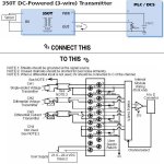
I want to connect a few 3-wire DC powered transmitters (Acromag brand) to an F4-04AD input module. Specifically this combination:

[attachment]

My best guess is the I connect:


Conditioner Analog
Output Module
-------------------------
P --> +24VDC
+ --> V and I
- --> C and 0V


Yes? No? Maybe?... :confused:

beerchug

-Eric

analog.jpg
 
You got it, the load and voltage symbol at the plc show it.
P=power in..ie +24vdc
+ = +dc voltage signal to plc
- = dc common
 
Thanks guys. I just wanted to be sure. Now, let's hope someone doesn't step in and disagree... utoh

ArikBY said:
Any particular reason not to think so?

Only because it's not one of the examples, so I wasn't 100% certain.

beerchug

-Eric
 

Similar Topics

Hey folks, I have a situation where I need to connect a 4-20mA transmitter to an AI card that only does 0-20mA. On top of that it only has 8 bit...
Replies
4
Views
2,428
I have a Allen Bradly Signal Conditioner card (931S-B1C6D-DC) hooked up to a strain gauge. The excitation voltage is 10V, the output is 4-20 ma...
Replies
8
Views
2,019
Looking for something I can’t seem to find. I use Automation Directs signal conditioners when needing to cleanup a 4-20ma signal and was wondering...
Replies
3
Views
1,325
Hello Everyone, Happy Thursday! I have a system, and 99% of my analog signals are 4-20 ma. I have 4 analog outputs that are 0 - 10V I have 4...
Replies
3
Views
1,431
I know of and have used the pot to analog signal condtioners. I am looking for the opposite. I need to convert a 0-5V (or 0-10V, or 4-20MA) to...
Replies
10
Views
2,821
Back
Top Bottom