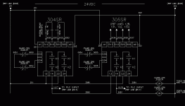
This is the ladder logic that will illistrate my crazy experience, last week.
[attachment]
OK, The circuit/logic was designed to tell the operator which safety gate is/was opened first. An alarm indication to a screen. If 304 SR contacts open, both inputs I:0/7 and 8 are turned off simutaneously, and N11:0/4 should latch. The EQU statement at the first of the rung prevents any other N11:0 bits latching in after the first one does.
If 305 SR opens, only I:0/8 is off and N11:0/5 latches, right???
That's the way things should work, here. If they both go away, I know the first in line did it, if only the second goes away, I know the second one did it. (by the way, the two circuits are combined so I could use one pair of CR's for two SR's instead of two pairs of CR's--both CR's are monitored by both SR's.)
But it didn't work that way. When I open 304 SR, N11:0/5 latches--then because of the EQU, n11:0/4 can't come in. If I remove the equ's, they both come in--/04 and /05. There are 4 pairs of gates wired/programmed this way but I see the problem only here on inputs /07 and /08.
The only explanation, I think, is that the /07 input "lingers" a little while longer than the /08 input when power is simutaneousl removed. A histogram displayed them as simultaneous, but the ladder will scan several times during the shortest histogram period.
Anybody got any other ideas??
The controller is an AB ML 1500 DC input type. And there are 5 of these applications installed. I have noticed this "inaccuracy" on one or two of the others, but only got a chance to chase it down last week. The only problem was hat the wrong guard was indicated as opened.
Anyhow, the result of all these hardwired relays is an MCR. So I wait till i see that gone, then wait .25 sec and check the gate inputs for the indication and that solved the problem.
But this thing proved to me that things are not always as they seem.


