Help with 1st. LL program please, sample code included.

snaggletto

Member
Join Date
Jul 2004
Posts
61
|		  |
| In1 Ls2 Out1 |
|-| |---| |---O---|
| |
| Ls1 Ls3 Out2 |
|-| |---|/|---O---|
| |
| Ls2 Out1 |
|-|/|---------O---|
| |
|-----|END RUNG|--|


Hello,

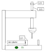
Be easy this is my first program. This is a basic program of how my drill machine is currently setup, except with limit switches rather than timers to control when 'activities' happen. I'm using Entertrons free software as an editor/simulator and the PLC programming book from this site, PLCs.net, as my guide.

*RUNG 1*

In 1 is a "cycle start" toggle switch.

Ls 2 is a limit switch showing that the drill head is safely retracted.

Out 1 is an output which triggers the air cylider to load a part. This needs to *STAY ACTIVATED* to hold the part while it's being drilled by Out 2.

*RUNG 2*

Ls 1 is a limit switch showing that the part is loaded into the fixture and is ready to drill. Triggered by Out 1 from the previous rung.

Ls 3 is a limit switch showing when the drill has fully punctured the part, and tells Out 2 to turn off (IE retracting the drill).

Out 2 is an output which triggers another air cylinder to advance the drill bit. This needs to STAY ACTIVATED until Ls 3 is hit. After Ls 3 is made, turn Out 2 off/retract the drill.

*RUNG 3*

Here is where I'm kinda stuck. Out 1 can only be enabled when the drill is retracted (sitting on Ls 2) for safety reasons. However, Out 1 needs to *STAY ON* while the drill is drilling (not touching Ls 2). Out 1 can only turn off when the drill is fully retracted again, (IE. hits Ls 2 the second time.) Then it all has to start over again automatically.

I tried to use a NOT Ls 2 to keep Out 1 on while the drill is not retracted. But, I think it just cancels out RUNG 1 and then does nothing.

According to my plcs.net programming manual, it looks as if I need a one shot or flip flop and/or an output latch. I can't seem to get it straight in my head. Basically I need;

While LS 2 is on, Out 1 turns on. Out 1 stays on until Ls 2 is hit the second time.

PLEASE DON'T give me the code. Just give me verbal recommendations/logic and I'll see if I can figure it out and right the code on my own. THANKS.
 
Last edited:
For formatting your code, before you start the ladder section press the 'LADDER' button you see above your reply in the section titled "vB Code". In the box that appears just type a single space then "OK". You'll get a pair of bracketed commands with 'ladder' written in them. Type between these commands using as many carriage returns and spaces as you need. Better yet, pre do your ladder using 'Notepad' then cut it and paste it into the space between these commands. Your spacing will be preserved when you post.
 
First thing, you have two Out1 outputs. Only the second one's state will be what the machine sees.

One of the things that beginners have a hard time adjusting to is that ladder is not a "stepping" language.
The machine doesn't do rung1 then rung 2 then rung 3. Try to think of each rung as an individual "task".
 
Back up a little. Instead of trying to explain your (non-working) ladder, explain exactly what the system is supposed to do.

You do a pretty good job with this part.

snaggletto said:
Out 1 can only be enabled when the drill is retracted (sitting on Ls 2) for safety reasons. However, Out 1 needs to *STAY ON* while the drill is drilling (not touching Ls 2). Out 1 can only turn off when the drill is fully retracted again, (IE. hits Ls 2 the second time.) Then it all has to start over again automatically.
[/B]

When you have a sequence written up, gather up all the conditions that make "OUT1" go on. Then do the same with your other outputs. Try to give names to your I/O and use them instead of "out1", etc. It will make it easier for you and others to follow.

It is often helpful to make internal bits represent conditions like "all returned" or "safe to load".
 
Ls 2, safe drill position limit switch, needs to be 'made' turn on Out 1, Out 1 needs to stay on (latched output?), then Out 1 turns off when Ls 2 is made the next time.

It needs to be programmed like a momentary ON/OFF switch for the same output, but the real switch isn't momentary. With Ls 2 being on when Out 1 turns on, and being on when Out 2 turns off seems illogical to me.
 
Don't try to look at the whole thing at once. Look at the sequence step by step. IOW, what has to happen to continue to the next step? There are a zillion ways to create a sequence. This is not how I'd do it, but it might help you figure out how to proceed... :confused:


|
| IN1 LS2
|----] [-------] [----+--------------( CLAMP )
| |
| CLAMP DONE |
|----] [-------]/[----+
|
| CLAMP LS1
|----] [-------] [----+--------------( DOWN )
| |
| DOWN DONE |
|----] [-------]/[----+
|
| DOWN LS3
|----] [-------] [----+--------------( UP )
| |
| UP DONE |
|----] [-------]/[----+
|
| UP LS2
|----] [-------] [----+--------------( UNCLAMP )
| |
| UNCLAMP DONE |
|----] [-------]/[----+
|
| UNCLAMP ?
|----] [-------] [-------------------( DONE )
|
|
|
| CLAMP UNCLAMP
|----] [-------]/[-------------------( OUT 1 ) Clamp Cylinder
|
| DOWN UP
|----] [-------]/[-------------------( OUT 2 ) Drill Cylinder


The Clamp, Down, Up, and Unclamp are internal relays (bits) to keep track of where you are in the sequence. The lower branch in each rung keeps the sequence bits ON (once they turn on) until the sequence is done. Notice the ? in the Done rung. What do you intend to use to signal that the piece is unclamped? Perhaps a timer?

The last two rungs control the actual outputs, based on where the sequence is.

beerchug

-Eric
 
Thanks for the reply.

I'm going to have to soak all that up for a bit.

There really is no need to know that the part is unclamped. When the air cylinder retracts, the part drops out and another takes it's place automatically (gravity feed). Getting the cylinder to retract, turning off Out 1 is the last step in the process. After that it all starts over and continues to loop until "cycle on" is turned off.

The "one shot" circuit; link

looks to act similarly to what my Ls 2 needs to clamp/unclamp Out 1. However, I think the state of Ls 2 would need to be "reset" for the start of the next cycle? Not sure on that one.
 
snaggletto said:
There really is no need to know that the part is unclamped. When the air cylinder retracts, the part drops out and another takes it's place automatically (gravity feed). Getting the cylinder to retract, turning off Out 1 is the last step in the process. After that it all starts over and continues to loop until "cycle on" is turned off.

If you have:

Last step: Turn OFF output 1
First step: Turn ON output 1

The output will turn OFF for no longer than 1 scan... utoh

I would think you need at least:

Last step: Turn OFF output 1
Wait for clamping cylinder to retract, finished part to fall out, and next part to enter.
First step: Turn ON output 1

A timer may be all you need. If that's the case, the timer fills in the "?" contact.


| UNCLAMP +----------+
|----] [-------------------------| ON-DELAY |
| | TIMER |
| +----------+
|
| UNCLAMP TIMER
|----] [-------] [-------------------( DONE )
|

beerchug

-Eric
 
I see what you are doing in your code, pretty slick. You are generating values at each step of the process then using them later to modify the outputs. However, when I attempt to "simulate" it in the free Entertron software I've got, it complains about "Clamp" as an output and "Clamp" as an input not being unique names, same for unclamp, up, down etc... How do I "carry over" the value of the output into an input on the next rung without using the same names? I was just wanting to visually verify each scan so that I thoroughly understand your code.
 
it complains about "Clamp" as an output and "Clamp" as an input

These are not physical outputs, they are holding bits, some plc's address them as C's, M's, Binary's etc...
I'm not familiar with the software you're using, but I'm sure someone will chime in about it.
 
I understand that they are maybe like user defined variables rather than actual outputs and inputs. From the "Learn PLC's" sectioni of this site, I thought I'd 'picked' up a rule that each rung of a ladder has to start with an input contact and end with an output coil. Maybe I just read into that and assumed incorrectly. I will do some searching, but I would like to study some more advanced ladder diagrams. Some that show some technique and styles. Thanks.
 
snaggletto said:
it complains about "Clamp" as an output and "Clamp" as an input not being unique names, same for unclamp, up, down etc... How do I "carry over" the value of the output into an input on the next rung without using the same names? I was just wanting to visually verify each scan so that I thoroughly understand your code.

That doesn't seem right. I can understand if you called both LS1 and OUT1 "clamp", it might have a problem. You should call LS1 "clamped" anyway as inputs describe a state not an action.

You should be able to use ouputs as inputs in a rung.

snaggletto said:
I thought I'd 'picked' up a rule that each rung of a ladder has to start with an input contact and end with an output coil.

You definitely can't have an output coil anywhere but the end of a rung.

However you can do

OUT1 OUT2
----| |------( )---


I have some other advice regarding you drilling application.

When you hit your full depth switch, but a run a timer for a fraction of a second before retracting to be sure you have come fully against the drill stop.
You are going to need some way to stop the cycle.
Some people put in an "Emergency return button" to return the drill in case of a misload. In a lot of machine tool applications, hitting an estop while machine will result in breaking a lot of expensive tooling.

 
Last edited:
Please refrence all these comments to the attached Jpeg example.

This is how I would start the program.........

Internal Relay 10 is used to automatically cycle the machine....Input 2 is your retracted limit switch (will not let output 1 clamp on until the retracted limit switch is made and Input 1 (toggle switch run/stop) is on. TC5 is a normally closed contact (From a delay timer) that you should condition to be made after the sequence has completed, after the delay is done it will unlatch output 1 and start a small delay to make sure to give enough time to load a new part, after this delay then set it up to give relay 10 a one shot pulse to activate the sequence and latch the output on, and start the sequence all over again.


And since you would just like some clues on how to do the program then I am going to stop here.....let me know if you need anything else......


David

screenshot003.jpg
 
Last edited:

Similar Topics

Hi, I have received a copy of a PLC program for a customers Carton erector that uses a beckhoff PLC and HMI. I just downloaded the trial version...
Replies
8
Views
2,265
Hi, I need to go Online w/ an existing ML 1100. I have RS Logix500 V7 and RS Linx V2.43. PC has PCMK card w/ no serial port but I have a USB to...
Replies
8
Views
2,798
Would someone be willing to help me get started.. I have a GE Fanuc Micro PLC that I need to program for the following sequence. PB Start Button...
Replies
2
Views
3,930
please help me . I have to make this ladder diagram and I can’t figure it out :(
Replies
11
Views
156
Hi Everyone, i was hoping for a little help with this module. i have data that needs to be read from a different plc through the Modbus plus...
Replies
11
Views
158
Back
Top Bottom