hi
If anyone is good enough to answer the question below please reply in a manner befitting an idiot
I have connected 2 modicon micros in a parent/child configuration to control a trimming system which removes the external weld bead on a newly formed tube
the problem is that a tube is made by welding coils of strip together, and these "cross welds" can break the trimming tools as they pass through the trimming system, and so the tools have to be disengaged for a second or 2, every 3 mins or so
in order to track the "cross weld" a blue sticker is placed next to it, and a colour sensor registers its arrival in the mill with a completely seperate schneider quantum, while an encoder/pulse wheel tracks its position, sending the pulses to a high speed counter in the quantum
what i need to do is get three seperate signals (events) from this counter to the modicon micros
a collegue at work tried to explain a solution to me, but my eyes just glazed over (I could see his lips moving but that was about it)
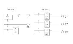
The solution I was given consists of two networks (attached) below is my understanding hopefully you can fill in the blanks
NETWORK 1 JPEG
The contact connected to the optical sensor closes as the blue sticker passes by, which closes the internal contact X and so latches itself. This in turn will enable the counter (not sure what that means in any detail)
I'm unsure what the "P" contact on the fourth rung is or does
Its connected to a counter register associated with the high speed counter which contains an exclusive OR gate which I think is used to reset the counter?????
NETWORK 2 JPEG
I was told the three internal registers are subtraction blocks used as comparison blocks????
These, store the number of pulses relevant to the set distances,
The fact that the output connection is in the middle of the block, and is connected to the top there will be an output when the counter is greater or equal the quantity in the register?????
Finally, after the last event the normally closed Y contact found in the first network opens and the first latch is lost
The cycle begins again, when the next blue sticker passes the sensor
Hope all this made sense
If you can shed some light on the above or need any more information, you can contact me at [email protected]
any help is very much apprieciated
cheers
Ash


