LD understanding 0 vs 1

hrohibil

Member
Join Date
Jan 2009
Location
Copenhagen
Posts
12
Hi everyone.

Happy new year to you all. Im glad to find a forum such as this.
I am new in the programming world of PLC.

I am selfstuding so my knowedge comes from books, internet and a short 2 days course I while back ago.

I want to understand the values 0 and 1 in relation to NO and NC inputs.

I have attached a simpel drawing of 2 ladderdiagrams. They basiclly do the same function, but the first ladder has a fail safe solution, so that the input signals are inverted from 0 to 1.

I allways thought that 0 was shut off and 1 was turned on, I mean how can NO input be 1. When a signal is 1 there should be current running to it right?

Can someone please explain to me from the first ladder from my drawing ( the left one) if I hit the S1/push button, how can there come an signal trough to the output V1, when the 2 lewel swithes LL and LH are Normally opened?

Can they be normally open and be a 1 signal?

Sorry for the long explanation, I hope someone can help me..

Best regards Hamid
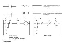
LD_jpeg.jpg
 
Hi everyone.

Happy new year to you all. Im glad to find a forum such as this.
I am new in the programming world of PLC.

I am selfstuding so my knowedge comes from books, internet and a short 2 days course I while back ago.

I want to understand the values 0 and 1 in relation to NO and NC inputs.

I have attached a simpel drawing of 2 ladderdiagrams. They basiclly do the same function, but the first ladder has a fail safe solution, so that the input signals are inverted from 0 to 1.

I allways thought that 0 was shut off and 1 was turned on, I mean how can NO input be 1. When a signal is 1 there should be current running to it right?

Can someone please explain to me from the first ladder from my drawing ( the left one) if I hit the S1/push button, how can there come an signal trough to the output V1, when the 2 lewel swithes LL and LH are Normally opened?

Can they be normally open and be a 1 signal?

Sorry for the long explanation, I hope someone can help me..

Best regards Hamid


In the PLC world, you have to think of those contacts backwards.

The NO contact uses the Exmaine If Closed (XIC) instruction. The instruction is TRUE if the input is closed (has power).
The NC contact uses the Examine If Open (XIO) instruction. The instruction is TRUE if the input is open (no power).

In your first failsafe example the level sensors have been setup to provide power (closed) if the levels are OK.
 
NO and NC come from relay terminology which shows the state of the contact when the relay is de-energised.

For limit switches etc, it is the same but here means when no force is applied to the switch actuator.

So a NO contact on a relay passes a signal when the relay is energised and a NC passes a signal when it is not energised.

With reference to your inputs, you are saying that when you start you are expecting to see a signal from certain inputs.

The term failsafe is used when you cover for loss of voltage or wire breakage in the real world. To enable something to work safely, you need to know that a certain condition is met. Therefore you wire it in a way that you receive the signal to know its safe.

A typical example is a high level switch, you only want to fill material if the container can accept new material. By wiring failsafe, i.e. get a signal when the high level is uncovered instead of when covered, you can ensure that you never attempt to feed into a full container.

If in the above case a wire breakes, then the NOT FULL signal is lost (which implies its full) and you do not put any more material in.

If you did not wire failsafe and you are looking for a FULL signal, a wire break would mean you would never get it and you would continue filling even when full.
 
Last edited:
In the PLC world, you have to think of those contacts backwards.

The NO contact uses the Exmaine If Closed (XIC) instruction. The instruction is TRUE if the input is closed (has power).
The NC contact uses the Examine If Open (XIO) instruction. The instruction is TRUE if the input is open (no power).

In your first failsafe example the level sensors have been setup to provide power (closed) if the levels are OK.

Only true for Allen Bradley, for example Siemens does not use the terms XIC and XIO.
 
Hi guys.
Thanx for quick reply.

Ok Peter,I will be using a Siemens S7-200, because I did not reconize the XIC and XIO.

I think I almost get it, but not completely. E.g Peter your example with the container filling, is somethibg similar to my 2 ladder drawings. I did not draw the complete ladder, but in the fail safe example I tried to ilustrate that the LL and LH lewel sensors have a 1 signal in dry mode, and when they get corvered they become 0. And if so a wire e.g breaks the signal will become 0 and thus can there not be filled any more.

So that I understand, but programmely I cant see it, when I look at my example with the fail safe mode, when I push the button S1, how can there come a signal to V1 óutput when LL and LH is NO??

Regards Hamid
 
Basiclly the program is written like this: S1 is the start button for starting the whole process. When the button is pushed, V1 opens for water into a tank. The tank has to lewel switches, LL and LH. When LH is reahed, it shuts of V1.

So I want my to LL and LH to be 1 as dry mode, so that when they are covered with water, they swithes to 0 and turns off. This way it is the fail safe mode.

But if I set the 2 input sensors LL and LH as a 1 signal, should they not be 2 normally closed swithes and not NO as in the fail safe drawing, otherwise how can there be an signal to V1 when the S1 is pushed??

i hope you know what I mean...

Regards Hamid
 
STOP-pushbotton's and basicly other switches who have a STOP-function should be hardwired NC, so in case of wire-break the program will stop the 'machine'.

start: NO-pushbutton
STOP: NG-pushbutton
 
IVO.

Yes I get the part with STOP buttons that they will be a NC contact, but please explain how can there come signal to V1, when my 2 input swithces LL and LH are NO??

So when I pres my start button S1, it will open a V1 water valve. But if my LL and LH is NO, there can not be signal to V1? I want to understand how to make them a 1 as active in dry mode, and when they get covered they loss signal ergo fail safe mode.

In my drawing in the fail safe mode, can the 2 LL and LH sensores be NO switches and be a 1 signal`

If anyone could upload something, it would be much appreciated.

Sorry for my ignorance in this field.

Hamid
 
1.
"Fail-Safe" terminology is usually considered to make a process stop in the safe condition should the input disconnect, due to a wiring problem, or device failure.

"Fail-Safe High" is typically applied to high-level probes that STOP a tank filling, in your case LH. It is usually configured to give a true input when the probe is uncovered (dry). In that way, if the wire were to drop off, the input would go off, which is the same as the tank filling to LH, casuing the filling to cease.

"Fail-Safe Low" is typically applied to low-level probes that STOP a tank emptying, in your case LL. It is usually configured to give a true input when the probe is covered (wet). In that way, if the wire were to drop off, the input would go off, which is the same as the tank emtying out, causing the emptying to cease.

If you analyse those statements, you will see that a LL is normally configured/wired 1=Wet, and a LH is normally configured/wired 1=Dry


2.
Both your logic diagrams are incorrect.

Including the LL in the rung would either prevent you from starting at all, or would stop the filling process when LL gets covered, not LH.

I assume that you don't want to be able to Start Filling, unless the LL is uncovered, as you have included it on the rung. If you apply the Fail-Safe High and Low principles above, the logic would be :-


START LL HL V1
|-+----| |----|/|----+----| |--------------------( )--|
| | |
| | |
| | V1 |
| +----| |-----------+


To allow V1 to energise, LL must be OFF (uncovered), and HL must be ON (uncovered).

If you want to be able to start re-filling regardless of where the tank level is, (below LH of course), then simply remove the LL contact from the rung.


START HL V1
|-+----| |---+----| |--------------------( )--|
| | |
| | |
| | V1 |
| +----| |---+


Ok daba.

Thanks for ilustrating. It makes sence, but strange since I got the example from a danish book.

But I can understand now why with the safty to make the high signal e.g as 1 in dry mode. This would cause it to stop filling if wires cuts and goes to a 0 signal.

I am beginning to think that I may have learning the flow to a rung the wrong way :-(

In your last drawing: you have a start button, a Normally Open HL and Output V1. So if I understand this correct, when you push the START button, a flow will run trough HL into V1 and energize V1?

I allways thought that to a flow to run trough you will have to have a NC switch. What if in your drawing there was a NC stop button?

Sorry im a confused about that part, if you start a button how will be able to energize it´s output trough a NC and a NO swithes?

Thank you again for drawing.

Hamid
 
First of all you need to know what kind of contacts are wired to the inputs before you start programming(and know when they are open or closed ).


Secondly; personally, like curlyandshemp, I find it better to think like this:

-| |-The instruction is TRUE if the input is closed (has power). The 'current of plc-logic' can flow further.

-|/|-
The instruction is TRUE if the input is open (no power).The 'current of plc-logic' can flow further.
 
Sorry im a confused about that part, if you start a button how will be able to energize it´s output trough a NC and a NO swithes?

Thank you again for drawing.

Hamid


START = NO-pushbutton
STOP = NC-pushbuton
START STOP V1

|-+----| |---+----| |--------------------( )--|

| | |

| | |

| | V1 |

| +----| |---+


Similar Topics

I am using Allen Bradley PLC for Ethernet/IP communication. I send any explicit msg request (Get attribute or Set attribute), I observed packet...
Replies
0
Views
70
Took a new job and the controls schemes are fairly old and I'm used to Allen Bradley and Siemens. I'm looking to replace a pair of Superior...
Replies
1
Views
105
Hello Team, I am desperate for some help with an assessment I have as part of a Level 3 general engineering course. I am in a role that is much...
Replies
9
Views
345
Good day is there somewhere i can see the situation and compatibility regarding different firmware revisions. I have a 2711-K5A5, series H and...
Replies
4
Views
212
Good Evening , I should know more about Solid State Relays . I have a system with 8) 120 vac Vibrators . These Solid State Relays have...
Replies
24
Views
2,051
Back
Top Bottom