Advice on ladder logic program.

MrNobody

Member
Join Date
Feb 2009
Location
Malaysia
Posts
22
Hi,
I have just started learning PLC programming by using TLP LogixPro Simulator. I'm now doing the Door simulation to Open and Close the door.

I've written the ladder logic program for the following scenario:
1) When the door is opening (Motor UP is rotating), pressing CLOSE button 1 time should stop the motor. Pressing CLOSE button the second time should close the door (Motor DOWN is rotating).
2) When the door is closing (Motor DOWN is rotating), pressing OPEN button 1 time should stop the motor. Pressing OPEN button the second time should open the door (Motor UP is rotating).

Note:
When either Motor UP or Motor DOWN is rotating, B3:0/0 (Moving Flag) is latch to high.

Some times the program doesn't work as in when the door is closing (Motor DOWN is rotating), pressing the OPEN button 1 time will cause the door to open (which is not what i wanted). The door should stop first and will only open when the OPEN button is pressed the second time. The reverse process also doesn't work.

Attached is TLP LogixPro Simulator code which I saved and also a print screen of the ladder logic code. Can somebody please advice me on how to make the program more stable and how to make it better.

Thank you very much..
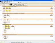
LadderLogic1.jpg
 

Attachments

  • Door-04-4.zip
    588 bytes · Views: 53
Okay,

First, you should have some kudos, some credits for the things you did right.

1. A + for using a flag as per the instructions.
2. A + for adding comments and descriptions to your program.
3. A + for getting the door to open and close in the "normal" mode.

Now for the minuses (-).

1. Although latching relays can be made to work to start and stop the motor, I do not prefer them for this problem. It is always possible that a novice will get the motor latched on with no way to stop it and it will trip out or burn up the motor. I prefer using a self-sealed output (interlocked with itself) that will drop out automatically.

2. Your flag bit only shows one bit of information, that the door is moving, but it does not show which direction. In this case your flag actually needs to confirm at least two pieces of information. For example, you need flag bits to show the following:

1. The door is moving DOWN AND the Open pushbutton has been pressed.

2. The door is moving UP AND the Close pushbutton has been pressed.

Now if you can figure out how to show both Item 1 and 2 with only 1 flag bit, then more power to you! I could not, and so used TWO flag bits in my version of this program.

I know of two good approaches to this problem, both using flag bits.
The first method is as outlined above, where the Open and Close switches are set up to have 2 functions, their normal function plus a stop function if the door is moving in a certain direction. A couple of one-shots (OSR) may be needed.

Door Simulator Ex 4 Method 1.jpg

The second method is simply to use the Open PB as a Stop switch on the Close rung, and to use the Close PB as a Stop switch on the Open rung. To do this you still need two flags, Going Up and Going Down.

Door Simulator Ex 4 Method 2.jpg http://www.plctalk.net/qanda/attachment.php?attachmentid=9896&stc=1&d=1237738494

Door Simulator Ex 4 Method 1.jpg Door Simulator Ex 4 Method 2.jpg
 
Last edited:
Another way to do it:

You could think of it as in a simple state machine:

State 1 Idle
State 2 Open
State 3 Close

Transition 1 From Idle to Open =
State1 AND OpenPB ONS ANDNOT Open limitswitch

Transition 2 From Open to Idle =
State2 AND ClosePB ONS OR open limitSwitch

Transition 3 From Idle to Close =
State3 AND Close PB ONS ANDNOT close limitswitch

Transition 4 From Close to Idle =
State3 AND Open PB ONS OR close limitswitch

State1 = (T2+T4+S1*!T1*!T3)+FirstScan
State2 = T1+S2*!T2
State3 = T3+S3*!T4

Outputs
MotorFw = S2
MotorRw = S3
Moving = S2+S3
 
As Lancie1 says, don't use latching contacts.
In real life the run contactor is normally sealed by an auxilary N/O contact and a N/C contact of one contactor is in series with the control circuit of the other.
Each button is also interlocked with the other.
 
Bara,

Good idea, but your states and transitions are not completely correct. For example, Transition 3 should not include State 3, but State 1 instead. Also there are some timing issues. For example, when going from State 2 to State 1 when the Close PB is pressed, your transitions will be this: State 2--> Transition 2 Open to Idle --> Idle State 1--> Transition 3 Idle to Close. It will not stop at "Idle" as it should.

Similarly, when going from State 3 Close to State 1 Idle when the Open PB is pressed, your transitions will be this: State 3--> Transition 4 Close to Idle --> Idle State 1--> Transition 1 Idle to Open. It will not stop at "Idle" as it should. The reason is because it is difficult to press the Open PB for only 1 scan. Therefore, as soon as Idle state is reached, the conditions are also met for the Transition 1 Idle to Open. I think these two problems could be fixed by not using the Open and Close PB's directly, but use each of them to trigger a separate One-Shot controlling a bit.

In this problem there is also a Stop Pushbutton I:1/2 which should always force the State to Idle.

This is a good illustration of how State Tables can help solve difficult logic problems, but the key is that ALL states must be completely and correctly defined, because state table logic becomes opaque and not intuitive to us old guys that learned using relay logic. I find it difficult to identify ALL possible states, because we humans tend only to look at the important ones and do not include all the hundreds or thousands of other possibilities.
 
Last edited:
Bara,

The first time I ran your unedited program on LogixPro, the motor did not stop at end of travel, caught fire, and the building burned down! Very funny to this old guy!

After making some changes to allow your State program to actually run on the LogixPro Simulator program that Mr. Nobody is using, the definitions look like this. The States and Outputs have the same definitions as Bara stated. OSR = One-Shot Rising.

OpenPB1Time = Open Pushbutton AND OSR#1
ClosePB1Time = Close Pushbutton AND OSR#2

Transition 1 From Idle to Open =
State1 AND OpenPB1Time AND OpenLimitSwitch

Transition 2 From Open to Idle =
[(State2 AND ClosePB1Time) OR NOT OpenLimitSwitch OR NOT StopPushbutton] AND OSR#3

Transition 3 From Idle to Close =
State1 AND ClosePB1Time AND NOT CloseLimitSwitch

Transition 4 From Close to Idle =
[(State3 AND OpenPB1Time) OR NOT CloseLimitSwitch OR NOT StopPushbutton] AND OSR#4

State1 = T2+T4+(S1*!T1*!T3)+FirstScan
State2 = T1+(S2*!T2)
State3 = T3+(S3*!T4)

Now it works, but it took me 14 rungs for this method, instead of the 7 rungs using my Method 1 or 2.
 
Last edited:
With OpenPB ONS i meant a OneShot signal from the pushbutton..

And yes T3 was wrong and some other things.. This wouldnt have happend if I had made a drawing of the states first and a I/O list.. But fast and sloppy does these things..

To make it fit in fewer rungs one could write the whole state equation in one rung that way we would get

2rungs for the OneShots (PbOpen,PbClose),
3rungs for the states (idle, open, close),
2rung for the outputlogic (motor fw, motor rw, door moving)

Then where down to 7rungs but I do prefer separating transitions and states.. Easier to change..

Just wanted to wake the idea of using state machines.. Knowing about these will make problems in the future easier to solve..

Maybe not the easiest way of solving this problem just another way..
 
Last edited:
Bara,

Thanks for your input. Yes I agree, this is another method to put into the bag of tricks.
 
To make it fit in fewer rungs one could write the whole state equation in one rung that way we would get

2rungs for the OneShots (PbOpen,PbClose),
3rungs for the states (idle, open, close),
2rung for the outputlogic (motor fw, motor rw, door moving)

Then where down to 7rungs but I do prefer separating transitions and states.. Easier to change..
Hi Bara, You mean, it is possible to cut the programming down to only 7 rungs..? I'm interested to learn the principles on how to do that.. Can you please explain more..?
Thanks..
 
Miscounted... Got it to eight rungs... Maybe used yor I/Os wrong but you get the idea..
See Attached file

For a great explanation about state based design one should look into Hugh Jacks free E-book..
http://sites.google.com/site/automatedmanufacturingsystems/

Note.. This soulution May not work for your certain CPU the explanation cut and modified from Hugh Jacks book is:

This method will provide the most compact code of all techniques, but there are potential problems.
Consider the example. If push button open has been pushed the line for OpenState should
turn off, and the line for IdleState should turn on. But, the line for IdleState depends upon the value for OpenState that has just been turned off. This will cause a problem if the value of OpenState goes off immediately after the
line of ladder logic has been scanned. In effect the PLC will get lost and none of the states will be on. This problem arises because the equations are normally calculated in parallel, and then all values are updated simultaneously.
 
Bara,
Just to confirm, your network 1 (FB1.pdf) on close button is similar to rung 1 of Lancie1's code (LogixPro Door Simulator Exercise 4 Method 3 .doc) right..?

In your code, is "#Pls2" state the same as Lancie1's "Open PB-1 Time" state..? And, what is the symbol -(P)- stands for..?

Also, is "#ClosePb_ONS" (your code) the same as "ONE-SHOT #2" (Lancie1's code)?

If the above are true then, the order of "#Pls2" and "#ClosePb_ONS" is your code is the reverse of Lancie1's code..
Can you please explain the difference as I'm abit confused..?
Thanks alot..
 
Bara,
Just to confirm, your network 1 (FB1.pdf) on close button is similar to rung 1 of Lancie1's code (LogixPro Door Simulator Exercise 4 Method 3 .doc) right..?
YES only that ive made it in Siemens never worked on an Allen Bradley..
In your code, is "#Pls2" state the same as Lancie1's "Open PB-1 Time" state..? And, what is the symbol -(P)- stands for..?
-(P)- Is a Positive edge coil..(Siemens)

Also, is "#ClosePb_ONS" (your code) the same as "ONE-SHOT #2" (Lancie1's code)?
YES

If the above are true then, the order of "#Pls2" and "#ClosePb_ONS" is your code is the reverse of Lancie1's code..
Can you please explain the difference as I'm abit confused..?

Just differences between different controllers all code after pls2 will only be executed for one cycle until next positive edge..
 

Similar Topics

Hi folks, I have a piece of code from my first project that I'm looking to improve a bit so am looking for some advice on how to do so. There's...
Replies
11
Views
2,840
Hi All, I was in the design stage of a new stand-alone machine and need some inputs/advice from all you experienced and knowledgeable industry...
Replies
5
Views
3,069
Hello: Goal 1. record time a sensor is on 2. delay signal for 3 seconds 3. send signal to motor and have it run for as long as the sensor did I...
Replies
64
Views
14,782
Excuse then punn, but i would appreciate any advice people would have about 'breaking in' to programming PLC's. Following an instrument...
Replies
4
Views
5,255
I am not sure why this is requested, but it was asked. Currently I have one PLC , with one output to a relay, turning on a field equipment (just...
Replies
7
Views
217
Back
Top Bottom