EMC / RFI type noise from Variable Frequency drive.

Join Date
Jun 2009
Location
Taipa
Posts
4
Just wondering if anyone has any experience with this issue

As part of a large installation we have a machine with 4 x 120HP 3PH motors each controlled by a SIEMENS SIMOVERT MC/P2 170A VF Drive.
These motors all seem to function correctly but we have been having issues with false prox switch inputs on the drives and PLCs for this machine.
I connected a scope to the signal return line from a prox out on the machine. Without the drives running the signal is dead flat, the moment the drives start there is all kinds of noise and interference on the signal, some times exceeding 30V (it as 24VDC prox)
This doesn't seem normal or acceptable does it?
The motor cables are all shielded and bonded to ground at the drive end. The signal cable to/from the prox is just normal un-sheilded wire.
As a second test I just lay a 30m length of 1mm wire across the floor near the machine and scoped that (relative to earth) and I see the same noise there too..... the other end connected to nothing!
Any help / thoughts on this subject would be much appreciated.
 
DO you have a reactor on the input side of the drive? I had very similar issue on a very large 32axis multispindle screw-machine. I had a coolant pump that had a VFD on it and everything in the machine would work fine until the coolant got turned on. I put a reactor in and problem is gone. The drives like to mess with the harmonics of the incoming and make the noise spread everywhere. Also installed RFI coils on the output just for good measure.

here is an article about VFD's and noise. http://ecmweb.com/mag/electric_line_reactors_vfds/

Hope this all helps.


Chris
 
Last edited:
The reason SkullZipper got his results was due to the output side filter. The input reactor is good for reducing power network harmonics but would not be expected to help much with RFI/EMI problems on the output.

The problem MattWaterhouse is experiencing is, unfortunately, not uncommon.

I understand that the installation already has shielded motor leads which is very good first step. However, it must be grounded at both ends. This actually forms a ground bond between two different grounds, the motor and the drive. Power grounding is not like instrumentation grounding where you must avoid shield currents by grounding only one end.

You probably will also need to run shielded cable for your prox switches and other low voltage signals. It's cheaper than buying a sine filter at these hp levels.

If all that doesn't get the job done, a dv/dt filter in the motor leads installed as close to the drive as possible is next.

Use the lowest carrier frequency in the drive that still keeps the motor quiet enough. Higher carrier frequencies usually make the problem worse.
 
Try connecting the shield at each end of the cable, (at the motor AND the drive) this is the only way for the shielding to be effective. Also the shield must be connected properly, best to use metal cable glands that are made to clamp around the shield and earth it, or earth plate with shield clamping
 
Matt.
Do you have a solid earth connection between the motor frame and the VFD chassis. This could be a fourth core in your shielded cable or a seperate earth cable run alongside it (check with Siemens for their recommendation). If you are using cable armour or the screen as your earth connection this has a relatively high impedance and the type of problem you are having is very common.
Andybr
 
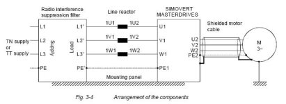
From Siemens Compendium Motion Control:

The high-frequency noise emission can only be reduced if the generated noise current is correctly routed. …
A shielded motor cable is absolutely necessary to enable the fault current to flow back to the frequency converter in a defined fashion. The shield must be connected to the housing of the frequency converter and to the motor housing through a large surface area. The shield now forms the easiest path for the noise current to take when returning to the frequency converter. A shielded motor cable with a shield connected at both sides causes the noise current to flow back to the frequency converter through the shield.

I'd like to add that the shield at the drive end should only be grounded at a particular point, namely PE2, this way the fault current will return directly to the drive.

Siemens.jpg
 
The signal cable to/from the prox is just normal un-sheilded wire.
As a second test I just lay a 30m length of 1mm wire across the floor near the machine and scoped that (relative to earth) and I see the same noise there too..... the other end connected to nothing!
Any help / thoughts on this subject would be much appreciated.


In the cable that has the prox signal, are there any spare cores that are unused , if so they should also be bonded to earth, this basically adds them to, or as, a shield in your cable, otherwise those spare cores can pickup signal noise, and induce it into the used cores, just as the wire that was put on the floor not connected to anything,
 
...just a thought, as I had a similar problem. Check that the prox. heads are the correct type for the PLC, i.e. current/voltage sinking/sourcing etc. Our system worked 99% of the time and a 'scope revealed a lot of noise so we assumed earth problems and ended up with massive earth cables joing up all moving parts of the machine. In the end, the prox. head manufacturer tech. guy had a look, changed the prox. head type and instantly all the 'noise' went! The giveaway was a flickery LED on the prox. head which lit solid when first covered by the metal flag but after a half a second flickered like a neon.
 
mattwaterhouse,

Another thought concerning the proxes themselves. If the noise is only bothering the proxes and They are "two wire" devices, try a three wire and see if the noise goes away.
 
Team! Thanks for you help on this I really appreciate it.

So to update to the situation:

- In the supply line to the drive there is a "AFE Cleanpower filter" Siemens, then what looks like a 3 phase choke, also Siemens.

- DickDV / GeoffC.... After some investigation I have found the shield on the motor leads has not been connected at the motor or at any of the other 5 motors on the machine. I'm thinking this is quite likely the problem or at least part of it.

-AndyBR..... Yep there is a seperate earth in the motor cable, 4C+sheild.

-Brownhat.... Ok, so the sheild at the drive end is bonded to a earth stud next to the drive in the cabinet. The drive is connected to this buy some pretty decent copper. But the sheild is not actually connected at point PE2. Thoughts?

Gil48.... Yeah there are several spare cores in the multi carring the prox signal. I'll bond them down to ground.

Robotman / mildrone.... I'm pretty sure it's not specific to the prox.... It is 3 wire and I also see the same noise coming back on signal lines from mechanical switches. It's just that the prox happened to be the input causing the most issues with machine function.


- Also another BIG question for you all:

What happens if the earth bar in the drive cabinet (where all these sheilds and grounds connect) isn't that well bonded to earth or the star point (N) of the main transformer?


- This control cabinet is 150m from the 11kV - 400V transformer.

- We are in China, well actually Macau, I'm not sure if it's a MEN system of supply here. Neutral may not be bonded to a earth peg or grid.

- The Neutral is bonded to "Earth" at the transformer.

- The only way this earth gets from the transformer to my control cabinet is via metal strapping / busbar attached to the walls of the building. It doesn't come direct either, it goes seems to go through about 10 other switch boards and motor control rooms.

- So the power feed comes direct from the switch board but the earth does not.

- I isolated the main feed and measured between N & E in my control cabinet, the meter wouldn't settle... It did read as low as 2ohm sometimes. N.B most of the plant was off at this time.

-It seems N is not bonded to E anywhere other than the transformer. Neutral is not used at the motor control cabinets.

So it seems this "earth" in the cabinet could be floating all over the show.... which surely is not ideal.

We have an extensive profibus network here which is notoriously unreilable.

If anyone has any thoughts on this earthing situation or what tests I should do to acertain weather this is a real problem I'm all ears.

Many Thanks,
Matt
 
Matt, the vagueries of Oriental 3-P supplies are familiar to me. Neutral is Earth at the Transformer wherever you are and in China my experience was to establish a good local Earth using one of the steel-framed building's legs, and seperate 'noisy factory' earth from 'clean electronics' earth. It was typical practice to ground the star point of motor wiring....

It may be of benefit to add the odd electrolytic capacitor across the DC control voltage power supply 'incomer' in the terminals of local junction boxes to which you have your prox heads connected. These will serve to get rid of AC noise and try to stabilise the local DC. I also resorted to pull-down and pull-up resistors, as appropriate.

Good luck!
 
Matt,
The manual shows the shield connection wired to PE2 at the drive. I've been told this is important because then the fault current in the shield returns directly to it's origin, i.e. the drive, without having to travel through the cabinet ground.
 
Great Success!

Ok Guys,

So just to update how this all worked out. I went through the cable run to the motors and found several areas in need of attention:
- Connected the screen at the drive end to PE2 at the drive rather than the cabinet ground point.
- Properly grounded the body of the termination cabinet along the cable path
- Properly ground the body of the motor isolator cabinet.
- Improved the connection of the motor cable screen as it passes through the motor isolator cabinet.
- Terminated the screen to ground at the motor where it was previously not connected.

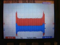
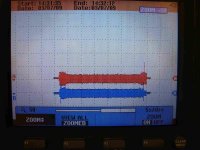
The results are good, general interference on my prox signial has reduced from 30V p-p to 5v p-p.

I've attached the pictures from the scope. Before and after. Red is my Prox signal return and blue is just a spare wire in a multicore which also runs out to the machine.

Thanks for all your help!

small1.jpg small2.jpg
 

Similar Topics

I am deciding on components for a bayed modular enclosure containing multiple VFDs (480V/350A/321Hp each) for a dynamometer. I am concerned given...
Replies
7
Views
1,714
Hello, I have a basic question. I am looking to order a PF525, and noticed they have an EMC filter option. What is the purpose for adding this...
Replies
4
Views
2,962
Hi there, Are there any experts or people with knowledge in the EMC and LVD testing here? if so, read on.. I have a display which is powered by...
Replies
2
Views
3,905
To make a long story short: I have two identical drives which have the same problem. The amp is a SEW Movidrive MDX61B-0014 (which by the way is a...
Replies
2
Views
1,569
K
Hi all. Tried to search on the forum but no luck. In my plant we got some problem with one of our gateways trips very often. And I now think it`s...
Replies
0
Views
1,415
K
Back
Top Bottom