Torque consultation..

theripley

Member
Join Date
Jul 2008
Location
laguna
Posts
545
Hi,

Kindly countercheck my physics..

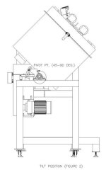
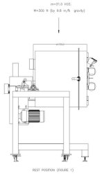
As seen on Figure 1, I have an identified load (N) & distance (mm) being tilted by a motor as seen on Figure 2..

Here is my simple computation:

T = Fd
= (300N)(0.7m)
= 210 Nm

Is this computation correct for my application?
I need the torque to specify my motor..
Thanks a lot..

PLCS-Model1.jpg PLCS-Model2.jpg
 
1.You need to determine the center of gravity (COG) for the object being lifted.

2.Then determine the distance between the pivot point and COG.

3. T[n/m] = Distance to COG[m] x Mass[N]

This would give an estimate torque that's needed to hold HOLD the box in position....
 
Last edited:
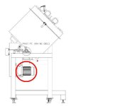
Is this the motor you are referring to ? You need to fully describe how the motor is coupled to the shaft that rotates the load to be able to calculate the motor torque. If the eqiupment is already built, make a torque wrench adaptor and measure the torque required to move the load at the motor shaft.

ripmotor.JPG
 
I believe that the torque will also be a function of the position of the overhung load. When it is straight up, there is no torque. When it is horizontal, the full weight at it's COG is being applied.

That would require the addition of "sin x" in the formula with x being the angle from verticle.

Of course, if maximum torque is the only value of interest, then the closest position of the load to horizontal would be max.
 
Is this the motor you are referring to ?


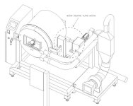
I am very sorry my bad..The motor that i am referring to is the directly coupled to the tilting axis (please see attachment)..

On my computation, I have considered the x (on sinx) that would give me the maximum answer, therefore x=90 & sin90=1..

I am very sorry for the confusion..Please pardon..

PLCS-3Model.jpg
 
Last edited:
DickDV,
you're correct. COG will change its position, so overall torque will depened of the angle. Therefore, there will be "sin" in the formula for torque.
 
There are two factors that should be calculated. So far you have only addressed the load due to gravity. The machine has mass and therefore intertia. This must be accelerated. If the inertia is not taken into account the ability to move the system accurately or at the desired speed will be hampered.

I have customers that use feed forwards to accelerated and decelerate the load. Then there is a sine function that that adds torque as a function of the angle to compensate for gravity.

Originally the VFD was setup in velocity mode but the VFD controls didn't work as well as using the motion controller to control the torque.
 
From a sizing perspective, you should start with Cobonweb's point about finding the center of gravity. The assumption in the original equation is that the total weight of the "box" is concentrated at a point 700mm from the pivot. This is obviously not the case. The original equation will always yield a static torque requirement greater than the actual torque requirement. How much greater is depends on the mass distribution, which is accounted for by determination of the center of gravity. Generally speaking, if the top of the box is very massive relative to the rest of the box the original equation will work. If the mass distribution is the other way around the original equation will the a ways off.

But don't discount Peter's point. Unless the goal is to just hold the box at an angle without moving it, torque requirements due to acceleration need to be factored in.

Originally posted by Peter Nachtwey:

Originally the VFD was setup in velocity mode but the VFD controls didn't work as well as using the motion controller to control the torque.

It's nice to have to available tools, isn't it?

Keith
 
From a sizing perspective, you should start with Cobonweb's point about finding the center of gravity.
Good luck. I have never seen a mechanical engineer provide a center of gravity. I have had people ask me how to determine the COG for Nascar racers and they spend millions on those cars.

But don't discount Peter's point. Unless the goal is to just hold the box at an angle without moving it, torque requirements due to acceleration need to be factored in.
Actually, you must address my point about the holding torque for all angles first.

If you try auto tuning this system it will fail unless the auto tuning can be done so that there is no load due to gravity. Otherwise the auto tuning system will look at the motion and the control signal to make that motion and assume that all of that control signal is required to accelerate or decelerate the load. Auto tuners don't understand changing loads due to gravity and orientation.

Ideally, one would find the control signal required to hold the load and subtract that from the control signal used in the auto tuning. This is the control signal required to accelerate and decelerate the load.

Most auto tuning systems are crude and are marketing tools just to say they have it instead of really being useful tools but I don't think there are any autotuners around yet that take into account the changing load due to gravity,,,,,,,,yet.

It's nice to have to available tools, isn't it?
Keith
Yes, and the knowledge to know their limitations and make them better.
 
Peter,
Did someone from NASCAR actually ask you how to determine the center of gravity of a race car?
 
Peter,
Did someone from NASCAR actually ask you how to determine the center of gravity of a race car?
Not NASCAR it self. From one of my customers makes test systems for NASCAR racing teams. I think I have posted links to the project.
Finding the COG empirically in 3D is hard. There is a lot of math involved and the mechanics but be tight and robust. I don't want to hijack the thread.
 
When moving the load that way, COG will change its position and will be sinusoidal function of angle. That is very nonlinear change that is acting like external disturbance. That is the reason why most autotuning systems will not work. For successful tuning disturbances must be kept at steady level which is not the case here.
 

Similar Topics

Hello, I have a motor that we are sending a RPM Speed Output from 0-100% to the VFD. However, the Motor HP needs to be limited to 6000 HP and the...
Replies
3
Views
91
I have always controlled servos in Rockwell motion using position loop. I have an application where one process will push against a servo...
Replies
3
Views
271
Hello, Would anyone happen to know what parameter in a PowerFlex 525 to have the drive trip if the torque permissive set point is exceeded...
Replies
3
Views
443
Possible dumb question here, but how does running a motor through a gearbox effect a VFDs ability to limit the torque on the driven load? My gut...
Replies
2
Views
523
Hello, I am posting this question (regarding drive control) on this PLC forum because I see that there has been discussion regarding this issue...
Replies
2
Views
613
Back
Top Bottom