Reading analog input in FX2N Mitsubishi PLC

pssriram16

Member
Join Date
May 2006
Location
San Francisco Bay Area
Posts
39
Hi All,

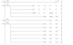
I am trying to collect data from an analog switch using AD module in a FX2N series PLC. I have attached my small code that I am using to capture the data every 10 milli second sampling rate. The AD module is in slot 6 of the PLC rack. Hence I am using K6 in rung 9951 as shown in the picture.

The actual sensor itself works fine since I am able to see the data spike from 0.2 to 5.2 . But I am not able to capture this transition in the PLC.

Please advice.

Thanks
Sriram
FX2N_PLC_AtoD.jpg
 
The eight "slots" are counted only for special function modules, so, first, is the analog module (IE: such as a FX2N-8AD) the sixth special function module in the row after the main block? If sdo, it would be device "5", not "6". If there are normal input/output modules in the string, don't count them. Only the special function modules. The code you show is FROM K6 K0 K2M583 K2. This would be the line that reads the information. What I would use would be: FROM K5 K10 D0 K8. This would read all eight positions into D0, D1, D2, etc.... Note this is for a module in special function block "6" on a 1 to 8 count, or No. "5" in a 0 to 7 count, which is what the actual PLC sees. Might try that. Any set of eight registers (D222 - D229?) will work in place of D0. This gives better results than trying to put the data into a set of coils. You're only asking for eight bits anyway. And then moving the bits into a register (MOV K4M583 D222) I haven't tryed to figure out what the rest of the MOV's are doing, but it looks like just trying to shift data ?
 
Been looking at your code again. First, the T25 is a 100ms timer. You need to use T200-T255 for a 10ms timer. Next you have two calls: TO K17 H0 K1 and TO K17 H1 K1. Both of those calls are attemptimg to write to input #8, which is K17 code. The from call K6 K0 K2M583 K2 but asks for it from a Input Mode setting, so it does nothing. It appears the first three instructions are probabaly going nowhere. The first two are writing to a Read point and the third is reading a point that should be written to.
Which analog input module are you using and what was your configuration written to it? There should be a one time call, such as:
Contact M8002 (first scan only) then TO H6 K0 H1234 K1 (which are the first four channels-numbered 1,2,3 & 4) in that sequence. The second four channels I do TO H6 K1 H5678 K1. The channel markers are, of course replaced by the appropiate setting codes, such as a "2" which sets the channel for -10vdc to +10vdc with a count of -10000 to +10000. Using a "0" sets the cahnnel for the same voltage range but gives a reading back of -/+16000. A "3" would give a 4-20madc input setting with a read back of 0-8000 counts. A bit more info and perhaps I can help a bit more.
I usually put the config write instruction near the front of the program where it's easy to find.
 
Reading analog input in FX2N Mitsubishi

Hi longshanks,

User Manual JY992D74701B
There is a program example. This is what I have used to implement the logic.

[FONT=&quot]FX2N-10GM [/FONT](servo amplifier) is in slot 5. "K5" ha already been used in the program code in reference to this servo amplifier module.

FX2N-2AD (analog module) is in slot 6. Hence I used K6 for my code.

Also the module is wired 4-20 mA.

I will also try changing the timer preset to 10 msec.

Thank you very much for your detailed reply. I will keep you updated on my progress.

Sriram


pssriram16: I have quite a few of the manuals in electronic form. I can send tham if you'd like. Contact me @ [email protected]
Any other help I can give, would be given gladly. Drop a line.
Don't have a 2AD manual, but do have a 4AD manual and I see they run 0-1000 count on a 4-20ma input.
 
Downloaded the manual for the 2AD and your code looks good compared to their example. Interesting how the different analog modules have such different code requirements. I've used the 2AD-BD, which is a horse of a different color and is no where near the same. I really like the 8AD module which has 3 different voltage scales and 6 different current scales. It will also do type J, K & T thermocouples direct in either C or F at 0.1 degree resoulation. It reads directly to D registers, which is nice. The 4AD module is similiar to the 2AD tho.
Still wonder about the module numbering you are using. The FX2N reads the special function modules as 0 - 7, not 1 - 8.... There is also a current limitation on the bace unit of 290ma from the 5vdc supply. What do your modules add up to ?? (the 2AD is only 20ma, while the 8AD is 50ma)
 
Hi longshanks,
The logic worked as given in the manual. Also tech support suggested using "RD3A" instruction. It works great too.
Also, the module numbering was '6'.
From left to right I have 48MT,1HC,1HC,4DA,10GM,32ER,10GM,10GM,2AD....now I had to guess which slot # is 2AD in. i am not sure how the specialty modules are counted. Anyways after trial and error slot # '6' worked well for me.

Also unlike in allen-bradley where we can configure the range of the current output from the sensor, I wasn't able to configure the 2AD module. The current output range from the actual sensor I am getting is 12 to 16 ma. So I am playing with the GAIN & OFFSET rotary switches in the actual module to give me a better resolution.

Thanks for the feedback.

Sri
 
Glad you got it working okay. For future reference, your modules count:
48MT(Base), 1HC(0), 1HC(1), 4DA(2), 10GM(3), 32ER(Ext Base), 10GM(4), 10GM(5), 2AD(6).....
Might help in the future. Confused me my first time also...
Longshanks
 
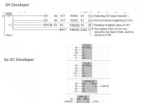
I have write the attached code for reading analog ch1 of FX2n-AD in GX IEC please verify it.will these K's M's will work with GX IEC developer.The above GX developer code is from manual.

analog ch1.jpg
 
Good day to all, i am begining the use of analog module mitsubishi. how about FX2N-4AD-TC? it the same program instruction to FX2N-2AD and 4AD and 2LC analog module? how can make an ON/OFF output and program the FX2N 4AD-TC? i have this unit attached to FX32MR PLC. can anyone who give me that sample program ladder? i will appriceate it
 
hi all

I am trying to configure three fx2n-8ad analog inputs(channels simultaneously).how can i write the program in gx-developer. actually i am new to mitsubishi. please anybody tell?
 
Sandeepplc, you will need to configure a hex address to buffer memory location #0 for channels 1 thru 4 and buffer memory location #1 for channels 5 thru 8.

So if you made an instruction bracket as follows: [TO K0 K0 H0363 K1] you are in effect writing to Special function module #0 (first K0, your location may vary) Buffer memory location #0 (second K0) -Ch4 as -10to+10V (H0xxx), Ch3 as 4-20mA (Hx3xx), Ch2 as -20to+20mA (Hxx6x) and Ch1 as 4-20mA. The last K1 is 16 bits written to the buffer memory location.

Does that make sense. The Hex address designations can be found in the manual for the FX2N-8AD which I found searching the Mitsubishi website www.meau.com (put the part number in the search engine). This information is in the manual's page 8-13.

Hope this helps.
 

Similar Topics

I am setting up a new system and have an s7 1214 plc with an sm1231 4x AI (6ES71231-4HD32-0XB0). It is configured for 0-10v and has no faults in...
Replies
5
Views
1,143
Hi all! Is someone can help me to understand what they means ? This is the only info I could find on my device : With this module is possile to...
Replies
5
Views
2,348
1762-IF2OF2 Analog Input Problem I use Micrologix1100 and explantion 1762-IF4 and...
Replies
2
Views
2,603
IM trying to find a cheap way to read system voltage using a 0-10 vdc input. my working voltage range is from 10-20 volts. Is there a voltage...
Replies
9
Views
4,469
Hi, How can I read and program for an analog input (4-20mA) from a Pressure transmitter. I'm using GE Fanuc's Versamax micro 23 point PLC...
Replies
7
Views
4,262
Back
Top Bottom