output leakage

jcole1

Member
Join Date
Dec 2007
Location
Kentucky
Posts
18
Hello guys and gals.

I have an older plc that has triac outputs. I recently installed new devices with solidstate inputs. The outputs from the plc turn on the inputs on new devices.

I think I might be having a problem with leakage current from the triac. I know if I put in an isolating relay the problems go away. So I assume leakage is the problem.

But, I have 48 outputs that need relays to work. Our SCADA system (plcs included) are in the design phase of getting upgraded so the relays would only be temporary.

Is there any cheaper way that I can get these devices to work without bying 48 relays and bases?

All replies appreciated.
 
You can look into instead of relays, putting a resistor (or Resistor/Capacitor setup for AC, I believe) in parallel to provide some draw down. The reason your relays are working is because their coil is putting enough of a load onto the output to draw it down.

I used to have some documentation somewhere about how to size the components properly, but I have misplaced it over the years. I'm sure it's floating around the internet though.
 
If you know the leakage of your triacs and the minimum turn on current for the inputs, you may be able to calculate and use load resistors in parallel. Be aware that when the outputs are really on, those resistors can get really hot, so the wattage needs to be carefully chosen.

If you go with relays, you may be able to use the terminal block type of relays to save both space and money.

http://www.bb-elec.com/product_family.asp?familyid=407
http://www.ab.com/en/epub/catalogs/12768/229240/229266/229643/229703/
 
jcole1,

Place 3w, 10k resistors across the loads that are having leakage issues. This will place an additional 12ma of load on the outputs and should swamp any leakage current. Just make sure the resistors are rated for the voltage they will see, and that all connections are properly insulated. Ohm's law says that a 10k resistor will dissipate 1.44w as heat when switched on. 3w parts should be fine, but if ambient temps are high, go with 5w units for the extra headroom.


-rpoet
 
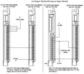
I have a SSR (triac) output card that says its maximum leakage current is 4mA. I have AC input module that says off state is <20VAC and On state greater that 70VAC.

If I were to use a 10k resistor then the Volts in off state could be 40VAC (=10k * 4mA).

So does that mean I need a resistor that would have a maximum voltage drop of 20VAC at 4mA (off state of output).
V = IR
20 =(0.004) * R
R = 20 / 0.004 = 5k

So that means with 120VAC in on state the resistor has I = V/R = 120/5k = 24mA. 24mA at 120V -> 2.88W

Is this right?
 
I'd give some more thought to relays on some outputs -
We just replaced a set of Symax's with Controllogix - one of the controlled systems was a set of hydraulic pumps and solenoid valves.
...short version of the story - solenoid valve faulted, shorted and melted the output card that it was switched by.
Bad design on the front end ? perhaps (I never saw the specs on the card and solenoid - I only learned all of this after I found the black soot marks on the panduit), but those solenoids were field devices in a coal-dust environment - a 10usd relay would have saved the 300usd output card and associated downtime...

finding the broken part is easy when its all black, deformed and smells bad.

-John
 
Greetings hanziou ...

well, your math looks OK – but you've left out one important thing ... an input module itself will present some amount of resistance/impedance/load to the circuit ...

take a look at page 8 at the following link ... even if these are not the specific modules you are working with, the general ideas should be helpful to you ...

http://literature.rockwellautomation.com/idc/groups/literature/documents/in/1771-in023_-en-p.pdf

survival tip: when you post a question like this to the forum, give us the specific catalog numbers of the parts you are using ... different hardware has different specifications – and one size (answer) does NOT fit all ...

I hope this helps ...

output2input.JPG
 
I would put resistors on all inputs to 0 volts not to ground.
anyway to avoid problems with ground loops and electronic outputs from devices (like a plc).
it is very annoying when you see 50 volts on an input.
some relais outputs have a capacitor and resistor so same problem.
 

Similar Topics

I have Automation Direct D06 plc with transistor outputs. What size, (ohms/watt) resistor should I use to connect neon lights to output, (120vac)?
Replies
6
Views
2,219
Hey all, I am starting a new project for a customer and I am adding in solenoid valves. Once added, I noticed there was a lack of an Output...
Replies
0
Views
67
Hi, The hardware is: Click Plc model # CO-O1DD1-O HMI model # S3ML-R magnetic-inductive flow meter model # FMM100-1001. I will set the flow meter...
Replies
4
Views
136
Hi, I am using AB 5069-L306ERS2 CPU. My system should achieve SIL-2. I have safety door switches connected to AB 5069-IB8S module, and I want to...
Replies
1
Views
108
Hello! Hope you are great. I need to make a change in a PLC with ladder logic. I will mount a analog valve and I need to control it in ramp up...
Replies
7
Views
318
Back
Top Bottom