Basic Start Stop Latch

Moosebreath94

Member
Join Date
Nov 2010
Location
MN
Posts
9
I am trying to learn PLC programming and I am currently working with AB Pico.

I need to stop a routine, and it would seem like the best way to accomplish this, in the spaghetti as currently nested, would be to use a basic "pushbutton stlye" start/stop latch. Instead of an operator pushing the stop button, I want to open the latch circuit with a timer or marker in place of I03.

I have tried quite a few combination's now but when I try to use a marker or timer, the latch just cycles on and off. I am beginning to think that this is related to the scan cycle.

The drawing is below, can anyone point me in the right direction?

Jim Herbert
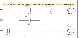
How to stop l.jpg
 
your start, stop, and timer logic all have to be outside of the routine you are starting and stopping. Otherwise when you take that routine out of the scan it can never go true again. Does that answer your Question?
 
Is your I04 Maintained? It should be a momentary TRUE to seal in M01. As long as it is momentary, anything that interrupts logic flow to M01 will drop it out completely.
 
RD,

Yes, I04 is maintained and now I see that as the problem with the cycling. Thank you.

The actual drawing is below. I have been struggling with different timers & markers at M10, where the problem with cycling was actually at M05. I will have to try to set and reset M05, unless anyone has a better idea.

Jim Herbert
Water Treatment Engineering

How to stop Il.jpg
 
Replace the M10 in line 27 with the timer contact (still NC) Once the timer is triggered (assuming the other conditions on the first rung are true and m5 is momentary), the timer will timeout and open the output. No need to use M9, it follows M6, just use M6 to start the timer. When timer times out, M6 will go off and reset the timer as well.
Not familiar with PICO, I assume the M's are internal relays.
Good Luck
 
Thanks Tommy,

As stated, M05 is not and will not be momentary. I guess I will need to set & rest it.

M09 is used elsewhere in the program.

Yes, M are AB Pico internal relay Marker bits.

Thanks for your input,

Jim Herbert
Water Treatment Engineering
 
Thanks Tommy,

As stated, M05 is not and will not be momentary. I guess I will need to set & rest it.

M09 is used elsewhere in the program.

Yes, M are AB Pico internal relay Marker bits.

Thanks for your input,

Jim Herbert
Water Treatment Engineering


If M05 is not momentary, why are you sealing around it?
 
Thanks, JBRW4GBM. I will do that

Moosebreath94: To remove clutter, fire M9 instead of M6. Redundant control relays will drive you nutz when troubleshooting- hard to follow. If your M5 is maintained, use a oneshot above the rung to turn the condition true for 1 scan which will latch in the output until the timer feels otherwise.
Good Luck
 
Thanks for the advice and direction Tommy. I will get to work on it.

JBRW4GBM: I have attached the zip file of my newbie spaghetti.

Jim Herbert
Water Treatment Engineering
 
For test purposes only, try this, use at your own risk, I have not tested this. I used your zip file as posted in post 10.
This sets up the one-shot that Tommy23t suggested.

On rung 14 position G change M05 to TT09 (Timer 9 timer), set the parameters to Single Impulse with constant set at 010.
On rung 27 position C change M05 to T09 (Timer 9 contact).

On a side note TT06 is set for 5 seconds, not 5 minutes as was indicated in the note on rung 27. I'm guessing that you probably set it to that value for testing.
 
Last edited:
JBRW4GBM: These changes work great! I just set the new timer for 5 sec to be in synch with T06. The timers are set in seconds for testing purposes.

Now I can try to close out the project with alarms and display.

I think my plan for the alarms is just to nest all the alarm contacts in parallel under the E-Stop contact located on line 3, position C, just like T04 is.

Thanks for your Help.

Jim Herbert
Water Treatment Engineering
 

Similar Topics

Hi all, I have a noob question regarding data handling from sensors. I understand configurations and I/O mapping sensor input/output variables...
Replies
2
Views
220
Hello I am new here and new to PLC's, I wrote this program for a class that I am taking and my local tech school. The description is switch 7 will...
Replies
0
Views
414
Hello I am new here and new to PLC's, I wrote this program for a class that I am taking and my local tech school. The description is switch 7 will...
Replies
10
Views
1,975
I’m a bit stuck on HMI (KTP-1200) programming… See the picture attached. The PASS or FAIL box should only appear when the toggle switch is...
Replies
7
Views
1,072
Hey Programmers, Heres todays puzzle I was trying to solve... I have a Modbus TCP network with two Modicon M221 controllers live on my work bench...
Replies
0
Views
467
Back
Top Bottom