ABB variable frequency drive & CAN-bus problem

noelie

Member
Join Date
Apr 2011
Location
Nijmegen
Posts
10
Hi, I'm new here, but I've searched everywhere on the internet and called everyone I know for support but no-one seems to be able to give me an answer.

Situation description:
I have a moeller XVC-100 PLC, moeller easy control EC4P-221-MTXX1 and a ABB ACS350 variable frequency drive with the FCAN-01 fieldbus adapter.
These components are all connected by CAN-bus.
To programme the XVC and EC4P I'm using Codesys SP2.

Problem:
The 2 eaton modules can communicate via CAN-bus (send and receive data). The ACS350 seems to be linked, but I can't send or receive the command or status words. When I switch off the XVC PLC or download a new programme into its memory, the HOST and NETWORK led light starts blinking red.
When I to the power back on or when I switch the XVC PLC into run after a new download, the Frequency drive detects that the host is back (HOST and NETWORK led light turn green).

What I've done so far:
I've gone through the FCAN and ACS manual about 100 times, checked all the parameters (especially Parameter set 51xx EXT COMM MODULE).
The CAN-bus slaves all have unique node-id's and the bus baudrate are all set to 125kbps.
I've added the FCAN .EDS file (FCAN-01_061B_ACS350_23xx) from the ABB website to my project. Addressed some extra information like the drive temperature into the Send PDO-Mapping, but still no information is sent.
I've called Eaton and ABB tech support but they both blame eachother for the problem and refuse to look into it any further.

I'm at a bit of a dead end now and beacuse this is for my Placement I really need to get this working.

I hope that someone can help me here and if additional information is needed please post and I'll reply asap.
 
Can you Read data from the ACS350??
Have you configured the network in Sycon in Codesys and allocated the I/O?

For the drive to accept commands it must be told to accept commands.
In the drive manual under fieldbus you will see a list of all the options available.
EG; to accept start the command from the fieldbus, parameter 10.01 must be set to 'comm'.
For any command to the drive its source must be set to 'comm'.
See Chp 12 in the manual. - tip ACS355 is a better manual, everything except STO is the same.

First of all thank you for your rapid resonse!

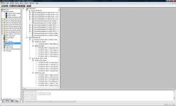
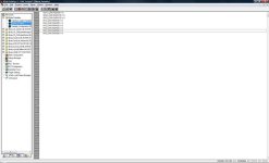
I can't read any data from the Drive. I've attached 2 screenshots: 1 with the PLC config and addresses and another with the values of these addresses when the PLC is in run.

All sources are set to COMM, sorry I forgot to mention this in my initial post.

I've also changed the transmission type of the PDO's (cylic, async, sync) but this doesn't seem to be the problem either.

PLC Config codesys.jpg Variable status.jpg
 
Parameters 0135 and 0136 show you the bit stream that the drive receives off the bus. With the CANbus active, you should be able to see the number in this parameter constantly changing as the bits stream by.

No change in this number usually means that the drive is not properly on the bus. Changes in this number mean that the bus controller is at fault. Often, the wrong register address is the cause.

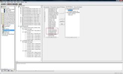
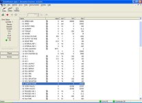
This indeed seems to be the problem. I've added another 2 screenshots: the first is a screenshot taken with drivewindow which shows that there is no data being sent over the CAN-bus (parameter 0135 and 0136 are always 0), the second is a picture in codesys. In codesys I can't address parameter 0135 and 0136.

Correct me if I am wrong, but it seems to me that the EDS drive file is incorrect as it addresses the wrong registers in the drive?
If this is the case, how do I address the correct register in the drive?

COMM Value Codesys.jpg COMM Value.jpg
 
There is a good chance that there is something wrong with the parameter settings in Group 51. I am not at all familiar with Canbus so I'm going to be of limited help.

If you don't mind making an international call, I would suggest that you contact ABB Tech Service in North America at 800.752.0696 or email them at D[email protected]. Ask for a Canbus expert. They are very good there and should be able to take this to a solution.

Alright, I think I've found the problem. Yesterday I found a new .EDS file. This file should be compatible with my FCan-01 firmware (101E) and drive firmware (257C).
When I add this file to my codesys project, contrary to the old .EDS I don't see any PDO maps and when I try to build with the new .EDS it says the Baudrate isn't supported.
I've changed the baudrate to test them all, but I keep getting the build error "Baudrate not supported".
I,ve compared both .EDS files in notepad and can't find any significant changes and seeing these lines in the file:
BaudRate_10=0
BaudRate_20=0
BaudRate_50=1
BaudRate_125=1
BaudRate_250=1
BaudRate_500=1
BaudRate_800=0
BaudRate_1000=1
I can't quite understand why I keep getting the build error "Baudrate not supported"

I've attached both .EDS files (changed the extension to txt), if you open them in notepad++ or anyother text editor (notepad) you'll be able to view them.

the old .EDS file is FCAN-01_061B_ACS350_23xx
the new .EDS file is FCAN-01_101E_ACS350_257C

Does anyone have any idea on how I can fix this problem?
 
Not all Baudrates are supported by the FCAN-01 - refer to the FCAN-01 manual.

I presume you have been thru the Quick Start guide in the FCAN-01 user manual???

Double check the drive settings as per the quick start guide again.

Operate the drive in local mode and check to see if the Status Word (SW) changes value - this is a good starting place.

I know that not all baudrates are supported, but when I choose a baudrate that is supported in codesys it still gives a build error "Baudrate not supported".
All drive settings (including CAN-Bus) have been changed according the Drive manual and FCAN manual.
I've been trying to see if I can see the status word (parameter 0135 and 0136) change whilst in local mode in DriveWindowLight, but no luck, the value is always 0.
 
Alright seems like I've got the EDS file working. The problem was that codesys didn't recognise the ABB EDS file because instead of using carriage returns in the file, all parameters were written in 1 long line of text.
Opened the EDS in notepad++ and re-saved this, added it to the codesys project et voila, a working EDS file.
But now I'm back to square 1 again, I still can't see any data change in parameter 0135 and 0136. I think I have a parameter wrong somewhere.
Anyone have any idea on what may be wrong?


btw if anyone is looking for the new EDS file for later project s. I've added it in this post as a .txt file. Just change the extension to .EDS and import in codesys. I've also reported the problem to ABB The Netherlands.
 
The command and status words are displayed at 0301 thru 0304. 0135 and 0136 simply monitor traffic on the bus so you will see changes but the numbers are meaningless.

But, it is true that if the drive is not communicating on the bus, you will see zeros at 0135 and 0136.
 
Sorry for my late reply, I was out on a business trip for the last week.
I've resolved some of the issues with the CAN-Bus.
The problem was that the transmission type in the PLC was set to: asynchronous - device profile spcific and the drive was set to: asynchronous - manufacturer spcific.
I can read the status of the drive (parameters 0303 and 0304 DCU Profile and ABB drive profile), I can write commands to the frequency drive with the ABB drive profile, but I can't write parameters 0301 and 0302 (DCU profile).
This is stated in the manual:
Because the DCU profile extends the control and status interface to 32 bits, two different signals are needed for both the control (0301 and 0302) and status (0303 and 0304) words.
When I look at the parameters of the drive using drivewindow, parameters 0301 and 0302 are locked. Anybody have any idea how to write a commandword?

If anyone is in need of the codesys project + drive parameter project just reply and I'll send it.
 
Last edited:
All parameters in Group 3 are read only. Both parts of the control word are modified by being written from CANBus. The status word is modified by the drive to report whats happening in the drive. CANBus reads both parts of the status word but cannot change it.
 

Similar Topics

Hi guys,need some help here please.I have an ABB variable frequency drive(second hand)and I need the user manual for it to set parametres and be...
Replies
2
Views
6,641
Variable Frequency Drive from ABB? This Variable Frequency Drive from ABB (number #ACS-101-2K7-1-U) was working just fine until one day this...
Replies
8
Views
10,120
Hi all, It is my first time using a VFD. The drive is connected to a fan which I need to run at variable speeds - ie. accelerate to a desired RPM...
Replies
8
Views
3,211
does anyone have an install or know if/where i can download it for the following "ABB PS501 Control Builder Plus V2.3 " the software was a free...
Replies
2
Views
89
Hello, It is mandatory to use VFD IF i use IE5 electrical motor? What happens If connect it directly as delta without VFD? Please look at motor...
Replies
1
Views
136
Back
Top Bottom