Scaling 1769 Microprocessor

jamalshahid

Member
Join Date
Apr 2011
Location
Tennessee
Posts
153
Hello Guys,

As of now i am able to know the equation for line ( for scaling y=mx+b) as b=0

y= 0.0009155*x+ b

My question is how will i know the value of X in above equation for scaling. i have tried searching this forum in some examples people are just assuming the value of X let say 31 or 41 means " We have to do trial and error"???? or what. My question is how will i find the value of x in order to determine scaled min and scaled max vaules for 1769 processor.

2)I am also using add on instruction how i have to figure out offset value after finding the scaled min and scaled max . Thanks
in advance. Please reply.

Regards,
Jamal
 
"X" is the raw data from your analog card. The range is determined by how you set up the card.

In your previous post the card was set up for -32767 to 32767.
Some can be set up for 0-16383, some 0-32767 or 4000 to 10000. There are others, it depends on the card. Tell us which analog card you are using and someone will post the manual for it.

See pdf below for an example for just one card. You the programmer will decide which range to use.
 
Last edited:
we are using -32767 to 32767
Please tell me the values of x for scaled min and scaled max means what i have to put in X. Also please tell me about off set thing. Thanks for helping me.
 
The pdf you posted: what is the scaled max 'X' value and min value in this pdf. If i am not wrong X is 16793 for both scaled min and max. Right? please tell me. Thanks
 
don't worry ... this is the last time I'll bug you with this ... I promise ...

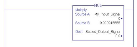
IF (big IF) the description that you gave for your original problem is correct, then the answer is as simple as the rung I've shown below ... if this does NOT solve your problem, then the forum members are going to need more information about how you've got your hardware configured in order to help you ...

PS EDIT ... can you ZIP and post the entire ACD project file? ... please just answer "yes" or "no" ... we ARE trying to help you - and we're NOT trying to confuse you - but honestly you're making this a lot harder than it needs to be ...

peace ...

.

mul_to_scale.JPG
 
Last edited:
jamalshahid,

I don't have the literary skills to fully explain all this. Hopefully the more skilled will jump in. I would recommend you find someone who can sit down with you and walk you thru this on a one to one basis.

Myself and others have tried to give you some guidance and also some links ( see below) to help with your questions. But all due respect you keep asking the same question. Please read the pdf's below very carefully.

http://www.ronbeaufort.com/y=mx+b_part1.pdf

http://www.ronbeaufort.com/y=mx+b_part2.pdf
 
Mickey and Ron!!

I am sorry for giving you hard time. But my friend i read the attached pdf. These pdfs are explained very well. My concept is cleared a lot by reading this how to use calculator and ..., but as i told you i am new to this plc world. I also attached program what outputs we are getting when i am using 0-200 transmitters.now we have to use -30 to 30. I wrote the straight line equation as you and Ron Explained me this. Thanks for that, but you told me that i need to do scaling in program as i am using 1769. That's what i don't understand how will i get X value as in these pdf which you asked me to read they are asking lets assume X is 31.
My input min is -32767
and out put max is 32767
to get scaled min i need x values please explain me one more time and what will be the changes in the below program and also how to set offset. I will take 10 minutes of your time but i am struggling with this from last 30 hours. Thanks for all your help.
 
once again ... can you ZIP and post the entire ACD project file? ... please just answer "yes" or "no" ...

and incidentally, you're not giving US a hard time - you're making this hard on YOURSELF ...
 
I need 0.3 on the blower by using pressure transmitters in range -30 to 30

I'm going way out on a limb here – but I'm GUESSING that what you mean by that statement is that AFTER you get the scaling done correctly, you're going to try to control the blower pressure by using something like PID control ...

if so, we're just getting started with this thing ... what's your deadline on getting this project done? ... note that ASAP is not a valid answer ...

do you have a working system (processor, etc.) on your desktop to experiment with – or is all of this just being "typed in" to be downloaded and tested out at a future date? ...

the more you can tell us about the entire system, the more detailed help we can offer ...

give us the details – and don't worry about making things hard on us – we can always just stop responding and ignore your posts if we get tired of this ...

we want to help, but so far you're making us just guess at how this project is supposed to work ...
 
yes, you may email it to me ...

note that I'm going to be offline soon - I've got other things that need to be done ... but go ahead and send it ...
 
Thanks for your support. I will send you my project file on your gmail. Please have a look. I need to replace pressure transmitters and want a value of 0.3
 
Greetings Jamal ...

first the good news ... I got the program that you emailed and was able to open it with RSLogix5000 version 17 ...

now the bad news ...

this application is a genuine mess ... before you go any further, you need to CONFIRM exactly what range and data format your field device (pressure transmitter) is using ... that will have to come from the manufacturer's documentation for that piece of equipment ... in order to move this discussion along, I'm going to assume (gosh I hate that word) that the device being used in the program you sent to me uses the following configuration:

4.0 mA = -407.853 (inches Water Column???) ...
20.0 mA = 830.397 (inches Water Column???) ...

this may or may not be true – but I can't tell from here ... the values are based on the setup in your existing program ... anyway - let's move along based on that assumption ...

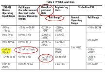
(1) whoever set up your SCP (scaling) apparently didn't go by the manual for the 1769-IF8 analog input module that you're using ... I've attached some of the most pertinent information below ...

DISCLAIMER: I have never worked with this particular model of analog module ... what I'm writing is based on how I interpret the manual (which might be wrong) ... possibly some other forum member more familiar with this module can confirm or correct me ... (I'll bet more than pocket change that I've got it right) ...

it looks like the original programmer (you?) chose to use the "Raw/Proportional Counts" format for each channel of this module ... that's unorthodox – but it's OK as long as it's done correctly ... (it is NOT done correctly in your existing program) ...

the book gives that format system a FULL RANGE set of values from -32767 to 32767 ... it looks like the programmer (incorrectly) interpreted that to be:

4.0 mA = -32767 data reading
20.0 mA = 32767 data reading

based on how I interpret the manual, I think the values shown above are incorrect ... working out the math, I think that the following values would be more accurate ...

4.0 mA = -29821 data reading
20.0 mA = 29085 data reading

in other words, based on a FULL SCALE range of 3.2 mA to 21.0 mA the values would be as follows ...

3.2 mA = -32767 data reading
21.0 mA = 32767 data reading

the CATCH is that most field devices do NOT range from 3.2 mA to 21.0 mA in order to neatly match the range of the PLC's analog input module ... so the values must be mathematically adjusted to work correctly ... apparently the original programmer missed that fact ...

summing up so far ... it looks like all of the original scaling was done based on the WRONG correlation of values ... (the old saying "garbage in – garbage out" comes readily to mind) ...

but it gets much worse ...

(2) whoever wrote those SCP Add-On Instructions got the internal formula wrong ...

this is the formula that's currently being used in the calculation:

Output = (((Scaled_Max - Scaled_Min) / (Input_Max - Input_Min)) * Input) + (Scaled_Min - (Input_Max * ((Scaled_Max - Scaled_Min) / (Input_Min - Input_Max))))

you should be able to correct the mistakes in this yourself ... if you need help, there are many forum members who can guide you ... personally I won't make any suggestions (for the reasons mentioned below) ...

(3) in the program you sent, each of your SCPs is followed by an ADD instruction which provides an "offset" to the results of the SCP ... the rung comment documentation says that this is done to "correct for inaccuracies" ... this is NOT the way this is supposed to be done – and in using this "offset" approach the flawed data becomes even MORE skewed ...

in other words, instead of tracking down the inaccuracies and fixing them, someone has tried to slap a band-aid on the problem – and in so doing has merely made matters worse ...

summing up ...

this is as far as I can go with this project ... you've asked for help on "how to scale" and I've done my best to show you where your problems lie ... this system appears to be related to "gas" flow and pressure control ... I can only assume (I still hate that word) that this involves some element of danger and I am not comfortable offering any suggestions on how you should go about fixing the obvious problems ...

I highly recommend that you make another post in this thread and give me permission to attach a copy of the program that you sent to me by email right here on the forum ... perhaps other forum members might be able to help you with your problems ... personally I'm not willing to make any specific suggestions on how to proceed based on what little I know about your system ...

I'm just guessing here – but I've got a hunch that you're trying to swap out one pressure transmitter with another in an effort to "fix" a problem with controlling your system ... I'll bet (pocket change only) that merely setting the original transmitter up correctly would go a long way toward solving the problem ... that's my best guess based on what little you've been able or willing to tell us about this project ...

finally ...

I have asked repeatedly for you to give us more information about this system – and about your involvement in it ... that information has not been provided ... this is the best I can do for you ... I truly hope that this has been helpful – and I sincerely wish you the best of success with your project and with your future career ...

in closing: give me permission and I'll post the program for you ...

.
IF8_ranges.JPG
 
Last edited:

Similar Topics

We use Function Block for most all of our scaling, and of course the SCL block for most everything. We also configure the AI in 4-20ma and...
Replies
9
Views
3,890
Hey everyone, Doing a project for a VFD fan controlling the temperature of the condenser at an arena. The VFD replaces a two-motor setup that was...
Replies
7
Views
2,758
I know this has been covered before, but I can't get this scaling to work in Logix Designer/CompactLogix 1769-L33ER project. I tried to: -...
Replies
4
Views
3,611
Hi All, I have this simple question. Please don't judge. How can I scale an AI from Analog module raw value to engineering value? I've searched...
Replies
17
Views
6,906
how to use 1769-hsc for requency input scaaling
Replies
0
Views
1,403
Back
Top Bottom