Relay logic help

Join Date
Jul 2012
Location
Singapore
Posts
51
Hi i have got a small project where i was asked to do relay logic for and annunciator panel.
The lamp should flicker incase of error,and when acknowledged with a pushbutton, it should be steady-ON.
How can do this by using relay logic. When reset is pressed after error is cleared, the lamp should be OFF.
It is the easy for me to do ladder logic for this. but i dont know relay logic.
Please someone help me:geek:
 
Are you buying the annunciation panel - most of them come with that feature built into them... Look up Ronan for an example... If you must do it with relays you will have to buy a cycle timer for the blinking portion of the circuit. The make cycle timers that fit a relay base. If you need a circuit drawing get back with me.
 
Hi i have got a small project where i was asked to do relay logic for and annunciator panel.
The lamp should flicker incase of error,and when acknowledged with a pushbutton, it should be steady-ON.
How can do this by using relay logic. When reset is pressed after error is cleared, the lamp should be OFF.
It is the easy for me to do ladder logic for this. but i dont know relay logic.
Please someone help me:geek:

Ladder logic is (generally)relay logic, if you can program simple latches and timers you have the ability to design an electrical circuit to do the same in the real world. Taking your electrical design and physically wiring it will depend on your electrical ability.

Cheers,
 
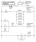
This is almost what you need.
The Lamp and the Horn go on if an error shows up. When acknowledged with a pushbutton, only the Lamp stays ON.
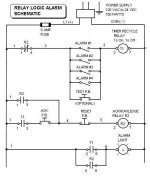
It only needs minor changes or you might like this one.
If one unit burns, you still have the other one! LOL
 
...if you can program simple latches and timers you have the ability to design an electrical circuit to do the same in the real world.
There are a few things that might cause a PLC programmer's relay circuit not to work.

For example, the typical relay has two DPDT contacts. Use more contacts than that, and you have to buy more expensive relays. You can get 3 or four equivalent contacts by carefully placing the DPDT so that one leg is common (see my R2 relay contacts above). Also, most PLC alternator logic ("flip-flops to those from Bugtulsa) will not work in relay circuits because there is no relay ladder sequence (one rung does not execute before another) - they all run all the time, unlike a PLC program. In relay logic, one-shot functions generally are not available (except for a few special-purpose relays). You cannot put relay coils in series and expect the circuit to operate.

Lancie1,

I referred only to simple latches and timers, which is all your schematic consists of. Of course there are some software peculiarities. My point was that by and large Ladder was a format designed to replicate an electrical format.

My only addition to Lancies Circuit is if you are doing an annunciator panel type application, with multiple instances of one fault = one lamp, rather than multiple faults = one lamp it would probably make more sense to have one flash timer with multiple contacts (or feeding a bank of relays) timers are generally more expensive than relays and this also has the added benefit of all the lamps flash in unison if you get more than one fault up at once

Cheers,
 
Last edited:
I referred only to simple latches and timers, which is all your schematic consists of.
Where did I use a latch relay? I agree that I used a timer relay, but I generally avoid latching-type relays for alarm control circuits. R2 is only a common off-the-shelf general-purpose Double-Pole, Double-Throw control relay, no latches needed.

It could be a difference in language. Perhaps in England, you call relays "latches"?

My only addition to Lancies Circuit is if you are doing an annunciator panel type application, with multiple instances of one fault = one lamp, rather than multiple faults = one lamp

"The lamp should flicker incase of error.." means that there is only 1 alarm lamp in this panel. I have built several using this very method, 1 lamp, multiple alarm inputs, except I did not use the reset button. I let the horn go off when the alarm was acknowledged but the alarm light blinked until the alarm was corrected or went away.

The flasher timer doesn't really need to have multiple contacts, only the normal 2. For relay-type circuits, the alarm inputs are all simply wired in parallel and connected to the timer relay coil.
 
Last edited:
Where did I use a latch relay? I agree that I used a timer relay, but I generally avoid latching-type relays for alarm control circuits. R2 is only a common off-the-shelf general-purpose Double-Pole, Double-Throw control relay, no latches needed.

It could be a difference in language. Perhaps in England, you call relays "latches"?


"The lamp should flicker incase of error.." means that there is only 1 alarm lamp in this panel. I have built several using this very method, 1 lamp, multiple alarm inputs, except I did not use the reset button. I let the horn go off when the alarm was acknowledged but the alarm light blinked until the alarm was corrected or went away.

The flasher timer doesn't really need to have multiple contacts, only the normal 2. For relay-type circuits, the alarm inputs are all simply wired in parallel and connected to the timer relay coil.


Hi Lancie1,

Yes it must be the language. If you check your quote, I haven't mentioned "latching relays" either. A simple latching circuit is what you are doing with your acknowledge rung using a normally open contact off your R2 relay to "latch" the R2 relay on until the reset contact is opened which unlatches the relay. I'm not sure what the American terminology would be for this type of operation.

Generally I don't use Latch and unlatch commands in PLC's where a traditional latching circuit can do the job, I find that it's harder for the maintenance electricians (used to electrical drawings) to understand how you can have several coils with the same address. Therefor apart from sequencing operations or anything special all of my basic PLC logic can be replicated electrically.

The original poster also said his circuit was required for an annunciator panel. If the long winded link I've posted below works, this is generally what I would class as an annunciator panel (1 light=1 fault): http://www.google.co.uk/imgres?hl=e...202&start=0&ndsp=16&ved=1t:429,r:11,s:0,i:102

You can buy these items as indicated, however they do tend to be expensive, I've used rectangular illuminated buttons in the past to achieve the same thing on small panels all be it using programmable relays (i.e. zelio, Logo) rather than hard wiring as I tend to find that by the time you've purchased a several timers and relays and spent time wiring it up you've probably spent more than putting in a smart relay which is easier to expand software wise.

I use a similar circuit to what you have posted above for beacons to indicate that there is an unspecified fault that needs further investigation (1 light=multiple faults).

Hope this clears things up,

Best Regards,

Lee
 
I'm not sure what the American terminology would be for this type of operation.
Contact seal-in.

The original poster also said his circuit was required for an annunciator panel.

It is the easy for me to do ladder logic for this, but I don't know relay logic.

What are the odds that a programmer that can do an annunciator panel logic in a PLC program would be assigned to design a relay-type annunciator panel? What would be the point when there are any number that can be bought cheaper than a custom-built panel? My bet is this only happened in a classroom for a project assignment. The instructor was probably wanting to teach the differences between relay logic and PLC logic. That was my only point, and so far it is a failure.
 
Last edited:
Contact seal-in.


What are the odds that a programmer that can do an annunciator panel logic in a PLC program would be assigned to design a relay-type annunciator panel? What would be the point when there are any number that can be bought cheaper than a custom-built panel? My bet is this only happened in a classroom for a project assignment. The instructor was probably wanting to teach the differences between relay logic and PLC logic. That was my only point, and so far it is a failure.

Hi,

Contact seal-in, I'll remember that one :nodi:

I don't think you have failed to make your point Lancie. but I do think we're both making assumptions on the original posters application and motives.

Best Regards,

Lee
 
send us your ladder in a pdf and we will make you a realy circuit.
(Just copy and send back, haha).
Yes, that is what most modern programmers think. We old farts know that it is not exactly that simple. I have built relay panels with 100 relays. You can't buy a relay with 100 contacts, although you can use one in a PLC program. With a bunch of relays in one box, you have to worry about the heat from the coils and how to cool the panel.
 
Last edited:
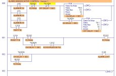
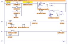
As an example of converting PLC programs to relay logic, here are two PLC programs that could be converted to relay logic. One will work with commonly-available off-the-shelf relays from your local electronics supplier. The other won't, even though the PLC programs work identically and produce exactly the same results. Which one can be converted easily?

Alarm Controls- Version 1.JPG Alarm Controls- Version 2.JPG
 
Last edited:

Similar Topics

please help i didn't solve this problem with rslogix. I counted but i am not using timer. How i will fix this situation? Please anyone solve this...
Replies
18
Views
4,917
Have a situation in an old pane which is controlling about 20items Conveyors elevators etc, where if the e-stop is pushed everything stops, OK up...
Replies
17
Views
4,643
CL-SOFT is a software for programming CL range Logic relay of ABB. But I can't find it. Pls show me, where can I download it! Thanks.
Replies
0
Views
7,177
Hello, can you help me implemetning the logic showed as ladder rung in the following picture? I need to realize it with classical and timer...
Replies
23
Views
7,921
Not sure I understand the logic here... This picture was taken when the rig was "idle". Why would you energise the trip relay M3 when these...
Replies
8
Views
1,249
Back
Top Bottom