HELP SOLVE PROBLEM USING WITH relay logic ladder diagram

oziken

Member
Join Date
Nov 2020
Location
İzmir
Posts
9
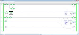
please help i didn't solve this problem with rslogix. I counted but i am not using timer. How i will fix this situation? Please anyone solve this.

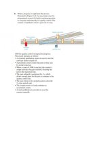
1000 for quality control or inspection purposes.
The circuit operates as follows:
• A start/stop pushbutton station is used to turn the
conveyor motor on and off.
• A proximity sensor counts the parts as they pass
by on the conveyor.
• When a count of 1000 is reached, the counter’s
output activates the gate solenoid, diverting the
part to the inspection line.
• The gate solenoid is energized for 2 s, which
allows enough time for the part to continue to the
quality control line.
• The gate returns to its normal position when the
2-s time period ends.
• The counter resets to 0 and continues to
accumulate counts.
• A reset pushbutton is provided to reset the
counter manually.
plc.jpg
 
Assuming that O:0/1 is the diverter solenoid, try using a NO contact (XIC) addressed to C5:0/DN in series with a NC contact (XIO) addressed to T4:/DN in rung 2.
Rung 2 will then be saying, When the conveyor is running and the counter has reached 1000 parts and the timer has not expired, turn on the solenoid.

Also replace the NC (XIC) T4:0/DN in rung 3 with a NO contact (XIC) addressed to C5:0/DN
Rung 3 will then be saying, When the counter has reached 1000 parts, let the timer begin timing.

You also need to program the reset pushbutton.
 
thank you it is working noww. This is very helpful. If there is a problem, can you help again?


yes, although the help should never be to simply give you the solution; you are taking a class, and the work should be your own as that is usually the best way to learn. our motivation for this is that you learn how to be the best programmer you can be, because some day you may be programming a machine that is dangerous.


Can you post your program? It would be interesting for others to see how you solved it.
 
Last edited:
If the OP utilized my suggestion, and assuming that the timer preset of 2 seconds is the typical spacing between adjacent parts, there is a small, but still nonzero, chance that another part might pass the photocell while the timer is still accumulating time, causing the counter accumulator to reach 1001 before being reset. Extra credit for the OP: Can you figure out a way to eliminate that chance?
 
If the OP utilized my suggestion, and assuming that the timer preset of 2 seconds is the typical spacing between adjacent parts, there is a small, but still nonzero, chance that another part might pass the photocell while the timer is still accumulating time, causing the counter accumulator to reach 1001 before being reset. Extra credit for the OP: Can you figure out a way to eliminate that chance?


+1 I was thinking exactly the same thing.
 
+1 I was thinking exactly the same thing.

I also spotted that.... My thinking is that the counting of the parts, and the timing of the gate solenoid should not be linked at all, and the counter should be reset at a different time than it is now - although the code as written follows the "flow" of the instructions .....


EDIT : @Steve Bailey : I see you covered that in your post....
 
Last edited:
A comment on the design of the system, which in the real world could matter ....

The part that is ejected (by looking at the drawing) will not be the 1,000th part to pass the proximity on the first occurrence only. Thereafter, it will eject every 1,000th part.

A suitable delay before energising the solenoid could cure this, but delays are sometimes not suitable at all, especially if the conveyor speed is not constant.

I would either :-

(A) use another counter driven from the same proximity, to introduce the "delay" before opening the gate ...

or :-

(B) Use a bit-shift register, clocked by the same proximity ...

Either way would work....

Also the time gap between parts would have to be longer than 2 seconds, otherwise the gate would collect more than one part.
 
My thinking is that the counting of the parts, and the timing of the gate solenoid should not be linked at all,...


Yup, although if two parts are that close together then two may get diverted, or possibly worse yet, the second one could hit the crotch of the Y.


But two parts close together is a bigger problem; presumably the diverter gate geometry and the 2s time delay come from an analysis of the how close two parts might be.


[update: daba already covered this]
 
Last edited:
I thinks its just a homework assignment and not really an engineered solution.
 

Similar Topics

Replies
49
Views
10,770
the logic will detect a if a part has been ejected from a stamping press. the program monitors a N.O. switch that is mounted on a cam which is...
Replies
4
Views
2,012
Q(1) Design a controlling system using DVP-40ES Delta PLC for a threestory Elevator Prototype as shown in the figure below. Show in details the...
Replies
4
Views
2,167
I have an issue with one pulse input. The LS0 is the sensors. The sensor stays ON one one of them and this makes the next step continuously gain...
Replies
1
Views
1,056
Back
Top Bottom