You are using an out of date browser. It may not display this or other websites correctly.
You should upgrade or use an alternative browser.
You should upgrade or use an alternative browser.
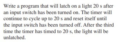
could anyone help me how to solve this problem via rslogix? thank you
- Thread starter ufomec
- Start date
drbitboy
Lifetime Supporting Member
I find it helpful to describe what happens to the pieces of the system:
so at time 0s, the input switch bit changes from 0 to 1; as long as that input switch stays at 1:
at time 20s, the light comes on and the timer resets itself for another 20s.
at time 40s, the light stays one and timer resets itself for another 20s and the
at time 60s, the timer has timed to 20s three times, and the light goes out.
Is that how you understand the problem statement?
Do you know how to make a repeating timer i.e. timer that repeats itself?
Do you know how the various properties (.PRE, .ACC, .DN, .EN, .TT*) of a timer change as it is timing? Can you extrapolate that to the case of a repeating timer?
Do you know how to make a counter count to 3?
* Allen-Bradley notation; other OEMs have similar property sets.
Steve Bailey
Lifetime Supporting Member + Moderator
You can't use 3 instances of the TON instruction with the same timer address, in your case T4:0. If you plan to use multiple timers, use T4:0. T4:1, T4:2, etc.
drbitboy
Lifetime Supporting Member
I tryed something like that but it does not work. thank you.
That is a good start, but it shows a few misunderstandings of what a timer is and how it works.
Delete everything except rung 0003, change the [XIC T4:0/DN] to [XIO T4:0/DN] and run it on a PLC or emulator and tell us what you see.
Then read the instruction help* for TON and tell us why that is what you see.
Why did I change the XIC to XIO?
Most importantly, can you figure out why you probably never see T4:0/DN become 1, even though from the evidence it must happen?
You are going to solve this, not us. But we will help you along the way.
* [Help button] => [Instruction Help button]
Last edited:
Steve Bailey
Lifetime Supporting Member + Moderator
The wording of the assignment suggests to me that the instructor wants you to use both TON and CTU instructions to get the solution.
Operaghost
Member
I'm with Steve on this. It sounds like you need just one 20-second timer and a counter that will count to three. But....forget about the actual code for now. Let's figure out the logic. Identify how it will work first, then write the code.
Think about what starts everything and what actions need to happen. For example, if I said the first thing that needs to happen is when you press the button a 20-second timer needs to start timing, what would you say the next action would need to be?
OG
Think about what starts everything and what actions need to happen. For example, if I said the first thing that needs to happen is when you press the button a 20-second timer needs to start timing, what would you say the next action would need to be?
OG
Last edited:
drbitboy
Lifetime Supporting Member
I did my first step like this. What do you think?
you are not there yet.
@OperaGhost and @SteveB: little steps?
try just this one rung
Code:
  T4:0/DN
----]/[-------[TON        ]---
              [Timer  T4:0]
[Pre 2s]- how it behaves,
- and why it behaves like that,
- and how you know that T4:0/DN ever becomes 1,
- and why you never see T4:0/DN become 1 (green).
Because that will be the core of the final program.
Use 2s as the preset for now so you can learn more quickly.
Operaghost
Member
Agreed, you're getting closer. But look at the first sentence of what you are supposed to accomplish. The light should energize after 20 seconds. When will your light turn on? Here is a good hint: Use your input to trigger the timer, use the timer to trigger the output.
And absolutely look at what drbitboy posted. It will be very important that you understand what it is doing.
OG
And absolutely look at what drbitboy posted. It will be very important that you understand what it is doing.
OG
drbitboy
Lifetime Supporting Member
drbitboy
Lifetime Supporting Member
I did my first step like this. What do you think?

Yes, as OG says you are getting close. In fact, if O:0/0 is not the output that drives the light*, then you are getting very close indeed!
Let me turn the question around back to you: how do you expect that code to behave? Don't run it, just look at it and think about what values the different parts (T4:0/DN, I:0/0, O:0/0, T4:0) will have?
* If O:0/0 is indeed only a placeholder bit that you want to latch to be a 1 so that the rest of the program will know that the timing and lighting sequence has started, then I suggest that you use the PLC-internal bit B3:0/0 instead of O:0/0. O:0/0 is an output bit, and outputs are limited and valuable resources that should not be used to maintain a single boolean state, which state could be maintained far more cheaply with a less limited and less valuable internal bit.
drbitboy
Lifetime Supporting Member
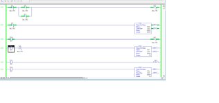
[Update I: corrected Rung 0000 per chelton's comment, even though it could go either way]
[Update II: fixed Rung 0001 also]
@ufomec
The way you have coded your Start/Stop circuit suggests you may need to review the concept. It may work for the current assignment, but it is not a best practice in the industry.
I coded two different approaches to Start/Stop circuits; see the image below. I suggest you ensure you understand how each works, and test them on real hardware to understand how they behave across mode changes and power cycles. Note particularly that latch/unlatch (OTL/OTU; set/reset for many non-AB PLCs) is neither used nor needed nor desired in the classic Start/Stop circuit.

Last edited:
Similar Topics
The ProSim-II Silo Simulation From the Simulations Menu at the top of the screen, Select the Silo Simulation
Exercise...
- Replies
- 9
- Views
- 5,894
I have an old PLC (circa 2007) consisting of Telemecanique/Modicon/Schneider Electric devices.
The system has developed errors and unfortunately...
- Replies
- 2
- Views
- 233
Hello,
I am trying to figure out how to create / write / delete a .csv file on the SD card of an Allen Bradley PLC.
There is a sample project...
- Replies
- 1
- Views
- 1,431
I have attached a picture. I just need to know if the option I've chosen is the correct one and if possible an explanation too. thanks
- Replies
- 14
- Views
- 3,652
Dear sir.
i have one Automation Direct hmi, if you have the CMORE Programming software,i will send you .eap file in email, can you please...
- Replies
- 3
- Views
- 2,441


