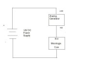
Microloix 1100 Analog input wiring.

kxs436

Member
Join Date
Jan 2011
Location
Boston
Posts
43
I am learning Mirologix 1100 and trying to connect a analogn 4-20ma generator. and using the SCP function to conver the 4-20ma input.

To simulate a tranmsitter

I connected +ve of analog generator to poitive of 12V DC power supply.

-ve of the power supply to I 0.4 of micrologix.

Com of microligx to -ve of the analog generator.

The analog generator has three options- VOltage, 4-20ma, Xmitter. I tried all three. Unable to generate 4-20 mA.

The I0.4 value is either always 1023 (max value) or 0. SOmething is wrong with wiring. COuld any one help.

Thanks
Karthik
 
I tried that too and I it dint work. No change of the values in the SCP functional block.

Should i configure the channel in RS logix?

The power supply is actually 16Volts. is the issues?

thank you
 
I'm sorry, I forgot that the analog inputs are voltage type not current.

Top provide a voltage input the generqator probably has hookups to both the positive and negative side of the DC power supply as well as an output (provide a link to the generator so we can be sure). Place the generator in voltage mode.

If you need to use it in current mode then place a precision 250 ohm resistor from the analog input of the Micrologix to the COM of the Micrologix analog input. The 4-20 ma current will then develop 2-10 VDC at the input pin.
 
the generator is powered by a 9 volt battery. the enerator has two wires and has three modes Voltage, 4-20mA, Xtransmitter.

threre is no other hookup. I am not sure what you are saying on how to wire.

thanks again
karthik
 
Because the Micrologix input is voltage - not current - use the setup in figure 1. No need for an external power supply.

And I don't understand figure 3. It seems as if the load polarity connections are backwards.
 
Last edited:
i tried fig-1 first before trying other things did not read any voltage. I will try it again todat evening.

So if its voltage input, is 0-10 volt the range ? what happens if input voltage is m>10volts.
 
The specifications list 'overvoltage protection' at 10.5 volts. The reading will probably stop rising (1023) at 10 volts. Try to avoiod going much higher.

Watch sthe actual input number and verify it is correct. Check the input with a secondary volt meter. Only after that worry about the performance of the SCP instruction.
 
Thank you very much for your time. one last question- Please let me know if i can wire the transmitter (attached data sheet) to micrologix. the data sheet says that output is 12-36 volt.
 
Use figure 3 titled 'Wiring to a PLC'. Especially note the 250 ohm resistor placed across the input terminals to convert the current (4-20 ma) to a voltage (2-10 volts) reading.
 
Does 20ma = 5volt dc

20/1000*250 ohm

then i can use a 500ohm resitor?

And for the singla generator I will apply about 0-10 volt across I0.4 and common and see if I get a reading.

thanks
karthik
 

Similar Topics

I have question about PID Being put into Manual I understand that placing PD?:/AM ON puts the PID into Manual mode, After that can I write...
Replies
2
Views
3,798
Hi all, I have to do communication between two ML-1400 through TP Radio (WDM 8000 data transreceiver). I tried to search realated information...
Replies
1
Views
2,731
Hi, I cannot find the DLCA1764.EXE utilty software for data retrieving. Can someone share the link to download this software. Thanks!
Replies
4
Views
119
I am currently backing a Micro Logix 1100 and no-one seems to have the file for me to upload from. Is there a way for me to upload the project off...
Replies
15
Views
520
I'm retrofitting equipment, but I didn't want to change the electrical characteristics of the panel. In this equipment I have a dedicated...
Replies
0
Views
68
Back
Top Bottom