You are using an out of date browser. It may not display this or other websites correctly.
You should upgrade or use an alternative browser.
You should upgrade or use an alternative browser.
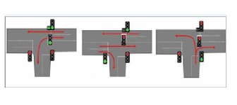
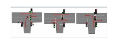
T-junction traffic light
- Thread starter taqwa
- Start date
hi andypot 
i'm using logix pro simulator .... i'm not driving on the wrong side of the road ..... i'm crashing it !! hhhhhhh
I really don't know how to start
I've been studying this subject for about a month and this is a homework
AND I DON'T KNOW HOW TO START
I will be really pleased if somebody can help
i'm using logix pro simulator .... i'm not driving on the wrong side of the road ..... i'm crashing it !! hhhhhhh
I really don't know how to start
I've been studying this subject for about a month and this is a homework
AND I DON'T KNOW HOW TO START
I will be really pleased if somebody can help
Hi Taqwa,
I don't think you will find anyone here who will do your homework, you need to make a start and give us something to work with, but to get you started I would suggest you give each of the traffic lights a name (or number), just something to identify them easily (it could just be 1 to 4).
I would then write down the colour sequences of all the lights (hint you have 13 lights) and the elapsed time. You can start anywhere but I would start with all lights red.
Example in the UK we have:
30 sec Red
5 sec Red and Amber
25 sec Green
5 sec Amber
Back to start
Another way to look at it:
0 to 30 seconds Red
30 to 35 seconds Red and Amber
35 to 60 seconds Green
60 to 65 seconds Amber
then back to start.
Don't try doing any programming until you have written down all the sequences.
There are many different ways to programme traffic lights, in order that we don't try to tell you a method that you haven't already studied let us know the PLC instructions that you have already been taught.
Good Luck.
Last edited:
Hi Andypot
I'm thinking to identify the three colors at first (red,yellow,green) , then use them when needed .... we've studied timers and counters ..... so I think that i should identify each color on a timer and start to do the ladder diagram ....... the problem that I'm struggling with is that I don't know how to control the four traffic lights at the same time (I can't find the best combination for the lights to work at the same time )
thank you for your help andypot
Last edited:
I would suggest you generate a table, as I said in my previous post you need to write down the sequence of all the traffic lights, ie when light 1 is green what colour are all the other lights? The most important thing to do BEFORE you even look at your PLC programming software is to generate a full specification of exactly what the PLC will do, this includes all the PLC sequences, how long each light is on, when it is on etc.
In a normal project you would give this specification to your customer and agree that it is exactly how the system is going to work. If you get it right at that stage then it is much easier to generate the PLC programme and more importantly you have a specification that you can use to CHECK and TEST the PLC operation.
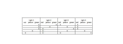
I have started a table in Excel - see attached, you could do something similar but you need all traffic lights so the table will be wider and longer.
Note my table uses British traffic light sequences, we go from Red to Red and Amber before going to Green, your country may be different.

Last edited:
The other thing you will need in your documentation (and it could be added to the table if you choose to use that method) is to identify any physical inputs and outputs you need to use.
You may not need any inputs but you certainly need outputs to drive those lights. Can you tell us where you will wire the lights (I know you are only using a simulator but you still need output addresses).
You may not need any inputs but you certainly need outputs to drive those lights. Can you tell us where you will wire the lights (I know you are only using a simulator but you still need output addresses).
Note my table uses British traffic light sequences, we go from Red to Red and Amber before going to Green, your country may be different.
This is the only thing that I would say is "slightly complicated" in this sense. It would be best to maybe use the more generic internation standard which does not have Red and Amber (having had experience with both I dont see how Red and Amber helps at all but thats a different conversation for a different day). Most generic traffic lights go Red - Green - Amber/Yellow and then repeat.
taqwa, I suggest you create the table that Andy suggested above (using your countires traffic light sequence) and post it here. That way we can correct it, if we see that there is an error.
this what the sequence should look like ..... i made the table andypot asked for ..... this made it much clearer for me but still i could not configure the way it should be connected to give these outputs .... i'm really confused
A few of comments on the table:
- Your missing a light you only have 12 lights but your photo shows 13! (4x Red, 4 x Yellow, 4 x Green, 1 x Green Arrow)
- Which Light is number 1 which is number 2 etc?
- What is the sequence of lights you are using? Is it British (Red - Red & Yellow - Green - Yellow), International (Red-Green-Yellow) or another variant. Some of your lights are going Red-Yellow-Green-Yellow and others are going Red-Green-Yellow.
- Third you havent completed the sequence totally. You need to complete the sequence and add the times for each step on the left.
Once you have corrected the table you need to decide which Light is the master, as in which Light will be the first to go green. Then based on that start programming the timers to create the logic
Taqwa,
You need to read all the comments from Usireland.
1. You have a light missing,
3. What is the sequence of your lights because they don't look correct. If you are not sure go outside and look at some traffic lights because the sequence does not look correct.
4. You need to add the times.
When you have finished look carefully at your table to ensure that the lights are going through the correct sequence.
When you are sure it is correct show us what you can do with a timer, forget the traffic lights for a minute, just write a couple of lines of code showing a 5 second timer and that timer turning on an output when it is done. We need to see you doing some code on your own because we can't do all your homework for you!!
a ladder can be in steps:
rung 1
ld not m1 (marker only off when starting) coil m1
marker m1 is only on for one loop.
rung 2
ld m1 set m2
rung 3
ld m2 and timer1.q (5 sec) set m3
reset m2
rung 4
ld m3 and timer2.q (25 sec) set m4
reset m3
rung 5
etc etc (i am not making your homework)
now for each step set the outputs
ld m2 out light1 green, light2 green, light3 red, light4 red
ld m3 out light1 orange etc. still not doing the filling in
greetings paul,
I suggest that you assign your LogixPro Output addresses in Slot 1 (0 to 16) like this:...i'm using logix pro simulator ....
Light 1: O:1/1 to O:1/3 (not using the green arrow).
Light 2: O:1/4 to O:1/6
Light 3: O:1/7 to O:1/9
Light 4: O:1/10 to O:1/12
Are you using the LogixPro I/O Simulator, or the LogixPro Traffic Light simulator?
Last edited:
Similar Topics
Hi. Does anyone have a traffic light program as stated above? Your help would be greatly appreciated. Thanks :)
- Replies
- 17
- Views
- 19,549
Hi all,
Recently, I had to segregate a large enclosure between AC and DC and interlock the AC Doors. I started thinking should this be applied to...
- Replies
- 10
- Views
- 2,231
i am new to these things. I have no intention of using this in a commercial way whatsoever. I wanted to write a small plc programme for myself. We...
- Replies
- 18
- Views
- 7,868
Hi!
We currently have a junction box and everything works fine, but one thing just bothers me and that is how I handle the cablescreen for the...
- Replies
- 3
- Views
- 1,366
Hi all, which terminals are you using for continuing shields in junction boxes without earthing them?
- Replies
- 3
- Views
- 4,672


