Hello,
I have been researching and experimenting trying to setup a PID loop for 6 conveyors that I need to sync with speed.
I am trying to get each conveyor to look at the conveyor in front of it and sync its speed to that one. So if Conveyor 3 stops then conveyor 4 will see this and stop, this will trigger a daisy affect so conveyor 5 will see conveyor 4 stopping and also following suit. This will also be useful for accel and decel as an operator will be adjusting speeds on the fly.
I am looking for help setting this up as it seems that not all my conveyors are responding to the conveyor in front. I am new to PID's and the Fb41 so I am looking for help in explaining what affects what and how I can properly tune.
From the encoders I have a DINT coming in.
This number ranges from 0-60,000 depending on the conveyor.
The slowest conveyor is just above a 30,000 reading from the encoder.
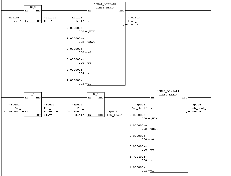
I have rotating knob that works as my POT at the operator station. This gives me a 0-10V based on the percentage the operator turns the knob. This gives me a reading of 0-27864 into the PLC on the 1st channel of the AI card.
I convert this to a DI and then to Real to prepare this for FB41 block.
This value is then scaled using the input 0-27864, with an output of 0.0-100.0, to give me the percentage.
My next step in an FB is to take the encoder value DINT (0-30,000) and convert it to a real number.
Next I scale this real number to a percentage.
I scale it an incoming value of 0-30,000 (as I want 30,000 to be the top speed for all the conveyors). This scale will give me a real output of 0.0-100.0 for a percentage of the speed.
I do this for all the conveyors so I know the percentage at which each conveyor is running from 0-30,000.
I believe I have the right time settings, and have had some help from tech support for these, but I am unsure how to double check and derive these numbers.
I am unsure how the gain is calculated and affects the output.
What is the best timing for the integral?
I have attached screen shots of my programming to explain.
If some could please help me or further explain things it would be much appreciated!
Hardware:
- CPU- 317-2EJ10
- AI- 331-7KF02
- (1 Channel enabled +/- 10V)
- 60hz interference frequency
- AO- 333-7ND01
- 0-10V Output
- COUNTER- 350-2AH01
OB35- Interrupt set to 100ms
Encoder- IFM RA 6029
- 1000 resolution
- 160KHZ
- Set to Single rotary Transducer 1000 pulses/rotation
- Rotation and speed measurement 10 x 10ms Time Window


 [URL=http://s1242.photobucket.com/user/NRTCEquipmentSales/media/pic1_zpsaf1fa9a0.png.html]

