Jasondelane
Lifetime Supporting Member

Hi all, I'm having trouble solving a problem I've been working on for several months, and thought you might like a stab at it.
The machine runs on a track, roughly 50 feet in either direction. It is manually controlled by the operator to move from 0-500 FPM in either direction using a joystick. There is no braking function. In order to stop or slow the machine an opposite control input must be made, or the machine will coast, eventually impacting the end stops which damages the machine. Under no circumstances must the machine hit these stops. The machine accelerates fairly quickly, reaching full speed in less than 3 seconds.
I am tasked with improving the control of the machine to within 20 FPM of a variable speed limit dependent upon process variables. Normal speeds are from 100-300 FPM.
Control must be performed with +-10 v Analog Output.
FPM speed feedback is being received with a 60ms update rate.
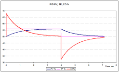
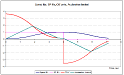
How do I use a PID or other control method to predict that I'm approaching my setpoint velocity and give just enough opposite input to slow it, and then hold that speed until the operator initiates a stop and reverses direction?
All methods I've tried have resulted in overshooting the target and oscillation of the PV around the SP due to the coasting nature of the machine and the inability to brake without giving an opposite input. Adjusting gains doesn't seem to accomplish it.
The machine runs on a track, roughly 50 feet in either direction. It is manually controlled by the operator to move from 0-500 FPM in either direction using a joystick. There is no braking function. In order to stop or slow the machine an opposite control input must be made, or the machine will coast, eventually impacting the end stops which damages the machine. Under no circumstances must the machine hit these stops. The machine accelerates fairly quickly, reaching full speed in less than 3 seconds.
I am tasked with improving the control of the machine to within 20 FPM of a variable speed limit dependent upon process variables. Normal speeds are from 100-300 FPM.
Control must be performed with +-10 v Analog Output.
FPM speed feedback is being received with a 60ms update rate.
How do I use a PID or other control method to predict that I'm approaching my setpoint velocity and give just enough opposite input to slow it, and then hold that speed until the operator initiates a stop and reverses direction?
All methods I've tried have resulted in overshooting the target and oscillation of the PV around the SP due to the coasting nature of the machine and the inability to brake without giving an opposite input. Adjusting gains doesn't seem to accomplish it.