PID Controller Design for Servo Motor by Using PLC

zee

Member
Join Date
Apr 2014
Location
penang
Posts
8
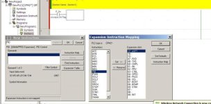
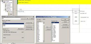
Hello, I'm student from Malaysian and currently doing a final year project about PID controller design for servo motor by using PLC. If you dont mind, I'm just wanna asking and need your advice about why my PID block always error and it describe that it 'not mapped' in my program??? I'm very sure that the destination of my PID block (input data word, 1st parameter word & output data word) are set rightly based on my PLC. For your info, I'm using PLC OMRON SYSMAC CPM2A and CX-Programmer...Here I attach my programme..tq
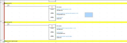
Untitled.jpg
 
Now I'm trying to control speed of servo motor. My program always have an error. If you don't mind, can you check my full program because I'm not sure with my own program. Before I connect it with my hardware, I really hope that my program didn't have a problem..=)
 
to help you,

you need to help us by provide the best info by picture,sketch,drawing,servo drive,cpu model,

we can give you few idea,hints other else you need do your own self.
 
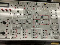
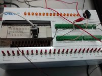
Okay, actually now my program totally can be use by using my PLC. I just want to ask one question about my hardware, is it can CE120 controller connected with PLC OMRON CPM2A??? Because I need to convert from analogue (CE110 servo motor) to digital (PLC) and vice versa. This attachment is the picture of PLC and CE20 controller that i use. TQ

IMG_20140506_115441305_HDR.jpg IMG_20140506_115501229.jpg
 
I no experience using the CE120, I need to read the manual user for handling.

if i not mistaken your first problem is CE120 already has its own PID, but no feedback entry.

if you program on CPM2A PID, then you have 2 PID.

if you want running servo motor you should have CE110, attachment.


You need expansion Analog Module CP1A-MAD01/MAD11 if you want PID-feedback applications.

CPM2A are old model.

except another model with Analog IO.

and you need 1 type of process to implement the PID .

Lot of examples of using PID - search on the internet.

I think you need to check/revise back of your hardware/project title.

now you using educational training kit.

you need 1 simple process.
 
I need to see a trace or trend to see what is wrong.
I don't know where the formulas for Ki and Kp came from.
It is easy enough to roll your one PI controller for speed control.
It looks like there is no encoder. Everything is analog.

What is the simulator supposed to be simulating. Only under damped second order or higher systems have a gain, natural frequency and damping factor. Usually the plant is modeled as just one gain and time constant or corner frequency.
 
Last edited:
Yes Mr PN. Can you explain more detail what are you mention above?
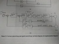
This give you my block diagram of speed loop.

IMG_20140507_242738662.jpg
 
Zee, what you have shown is a cascaded loop control with a PI controlling the inner loop and a PID controlling the outer loop. Current loops must be relatively fast. Are you trying to control this cascaded loop with a PLC?

The encoder pulses should not be converted to analog. The velocity should be determined directly from the encoder count rate.

Do you need to use this equipment? Can you use something else?
 
Mr. PN, if I'm not converted the encoder pulses to analog, actually my servo motor trainer CE120 cannot move when I give the input at PLC (because the motor is in analog state). So, input from PLC cannot give a real command to my servo motor because of 'interruption' here. And I only have this equipment to do the experiment.
 

Similar Topics

Hello guys, I suggest to play a little for Friday night quiz. Objective is to design PI controller that will provide "good" response of the...
Replies
18
Views
12,205
I have an old Chinese Temperature PID controller XMT 8038c2kp that am able to send and receive requests via Modbus poll test center in this format...
Replies
0
Views
442
I have a question regarding the features of the so called incremental (velocity) form of the PID controller. As far as I understand this form in...
Replies
14
Views
2,525
Hi - I have an application where there is an option to use a PID loop embedded in the Transmitter to directly control (via 4-20mA output from the...
Replies
4
Views
1,069
Hi All, I have a PID control application that I would like to get your opinions on. As I am reality new to PID loops I am struggling somewhat...
Replies
14
Views
4,285
Back
Top Bottom