Parker 590 drive to Siemens 300 over Profibus

Outrage

Member
Join Date
Jul 2006
Location
Nottinghamshire
Posts
173
Hello, I'm trying to configure Profibus communications between a CPU315-2 PN/DP and a Parker 590 DC drive fitted with a L5353 profibus card.

I've got as far as installing the GSD in Step 7 and looking through the profibus manuals off the Parker website but quite frankly the method of parameterisation is stumping me, plus all of Parkers example documentation seems to display COM-Profibus examples which seems a bit old hat and I'm strugging to transpose that into Step 7 HW Config format.

Does anyone have any parameterisation configuration examples they can post? I have a support call in with Parker at the moment in which they have given me reference to the parameter tags I require and pointed me in the diection of the manuals which I already have.

The drive has been supplied, configured and installed by Parker onsite and I don't have access to it until commissioning starts. so any help would be appreciated!

I've around 20 other devices hanging on the same network ranging from digital meters to torque transducers that have all been well documented but this kit is something else...

Cheers,

Lee
 
The first thing you need to do is figure out which tags you willneed to read and write from/to and convert them to Hexadecimal.

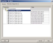
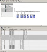
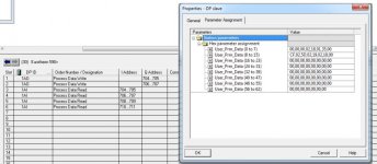
You then need to set the configuration in HW Config by right clicking on the slave, select properties and then open the configuration tab. See attached picture. Enter the hex codes for the tags required in the right order and matching the hardware congig.

This seems very arcane these days but wasn't uncommon when profibus was invented.

Next comes the fun part of trying to read and write data to the drive. Unless Parker have changed it (which I doubt) there are some limitations to be aware of with these drives on profibus: you can only send/reciece two bytes of contiguous data, you can only send/recive a 16 bit number i.e. no double integers or floats.

I've attached the source code for a block that breaks up an area of contiguous data from a data block and sends/recieves it as smaller chunks. In this way instead of sending 16 bytes to a 590 drive you can send 2 bytes 8 times.

The 590+ drive is, probably, the best stand alone DC drive money can buy so don't be put off by the quirky Profibus implementation.

Nick

Parameter Assignment.jpg hardware config.jpg
 

Attachments

  • fcPartComms.txt
    3.7 KB · Views: 218
Hi Nick thats great information, thankyou!

I'd had a look at the parameter assignment screen and concluded that was probably what I needed to do but I didn't know how the data tied into the hardware configuration so thanks for clearing that up, it's quite a gamble to make when you don't have any hardware available for testing. Is there anything special setup under each slot of your hardware config?

Thanks for the block as well, I had'nt been made aware that we couldn't read contiguous data although I have come across something similar on my network for one of my torque transducers. Siemens isn't my native PLC neither is STL, so I'll digest what you've sent and may need to come back to you with a few more questions about your block. Do you have any examples on how you've used it in your code?

First Parker drive i've done and it does seem a bit heavy going on the comms but it's been supplied by another company so I don't have much choice but I'm sure it'll be fine when we get on site.

Thanks again,

Lee

(edited for dodgy spelling)
 
Last edited:
I've attached the source code for a block that breaks up an area of contiguous data from a data block and sends/recieves it as smaller chunks. In this way instead of sending 16 bytes to a 590 drive you can send 2 bytes 8 times.

Hi Nick, Having looked at your code with my untrained STL eye...

Are you in effect using the DPRD and DPWR instructions once, incramenting the pointer addresses each time? I only have a few bytes in either direction... for simplicity can I use a chain of DPRD/WR instructions executing ech time the previous one returns no error code? I know it's not as elegant as your solution and given the same task in Rockwell I'd go the same way! but the learning curve vs time for this "simple project" has been gradually eroded away.

Cheers,

Lee
 
Are you in effect using the DPRD and DPWR instructions once, incramenting the pointer addresses each time?

Yes, your interpretation of how it works is correct. You could, of course, handle the comms in many ways such as multiple calls to SFC14/SFC15 or even multiple L DBX.DBWX, T PQWXXX.

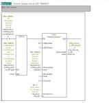
I don't write code any more but when I did, I always tried to write code that might be useful to me tomorrow for something else and that is how the fcPartComms came to exist. It has been deployed many many times since it was written. The example attached is taken from a single project that calls this routine 28 times.

The previously attached code is an STL source file. To use it: 1) change the file extension to .AWL 2) Open the Sources folder in your S7 Project 3) Right click and select "Insert new object" / "External Source" then select the .AWL file. 4) Add an entry in your symbol table for "fcPartComms" to a vacant FC number. 5) Right Click on the source file and select compile. All being well, a new block should now exist in your blocks folder corresponding to the number enterred in the symbol table.

Nick

PartComms.jpg
 
Yes, your interpretation of how it works is correct. You could, of course, handle the comms in many ways such as multiple calls to SFC14/SFC15 or even multiple L DBX.DBWX, T PQWXXX.

I don't write code any more but when I did, I always tried to write code that might be useful to me tomorrow for something else and that is how the fcPartComms came to exist. It has been deployed many many times since it was written. The example attached is taken from a single project that calls this routine 28 times.

The previously attached code is an STL source file. To use it: 1) change the file extension to .AWL 2) Open the Sources folder in your S7 Project 3) Right click and select "Insert new object" / "External Source" then select the .AWL file. 4) Add an entry in your symbol table for "fcPartComms" to a vacant FC number. 5) Right Click on the source file and select compile. All being well, a new block should now exist in your blocks folder corresponding to the number enterred in the symbol table.

Nick

Hi Nick, thats cracking pal! thanks very much for the block, I'll transpose it and go with your method now I think, seeing it in the flesh looks quite straight forward.

Yes I know what you mean about the multiuse blocks, I've got stacks for Bradley, but I don't tend to do so much Siemens at the moment and my Siemens blocks are generally process and control related, and don't tend to cover comms. I'll add this to the arsenal thankyou!

Best Regards,

Lee
 
Yes, your interpretation of how it works is correct. You could, of course, handle the comms in many ways such as multiple calls to SFC14/SFC15 or even multiple L DBX.DBWX, T PQWXXX.

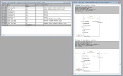
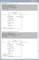
Hi Nick, I wondered if you'd have a few minutes to cast your eye over what I've done in my software using your block. I've attached a couple of images, the first is my ladder and the structure of the datablock, the second is the Hardware configuration.

It seems to make sense to me, but I'm keen to avoid any surprises once I get to site.

Cheers,

Lee

Drive_Read.jpg Drive_Read2.jpg
 
OK that looks about right.

I don't have a 590 manual to hand and can't see the difference but I've previously sent the speed demand to 01,53 rather than 01,35. Your implementation of fcPartComms looks spot on.

One other thing I'd recommend is to use a UDT for your send and recieve data with the control/status word bits expanded as a structure. See examples below.

Oh... and one more thing. Don't forget to turn on bit 10 of the control word or the drive will ignore everything elso over profibus.

Good luck,

Nick

Code:
TYPE "tDriveReadData"
VERSION : 0.1
 
  STRUCT  
   DRIVE_STATUS_WORD1 : STRUCT  //Drive status word 1
    bSpeedDeviation : BOOL ; //Set - Act > Tolerance
    bControlRequested : BOOL ; //Sequence - Control Requested
    bCompSpeedReached : BOOL ; //Comparison Speed Reached
    bNotTorqueLimit : BOOL ; //NOT Drive in Torque Limit
    bHoldinBrakeOpen : BOOL ; //Holding Brake Open
    bNotMotorOverTemp : BOOL ; //NOT Motor Over Temperature
    bMotorReverse : BOOL ; //Motor Reverse Direction
    bNotDriveOverTemp : BOOL ; //Not Power Unit Thermal Overload
    bReadyToPowerUp : BOOL ; //Drive Ready to Power Up
    bReadyForOperation : BOOL ; //Drive Ready for Operation
    bDriveEnabled : BOOL ; //Drive is enabled (running)
    bFaultActive : BOOL ; //Fault Active
    bCoastStop : BOOL ; //No Coast Stop Active (OFF2)
    bFastStop : BOOL ; //No Fast Stop Active (OFF3)
    bPowerInhibit : BOOL ; //Power on Inhibit
    bFaultActive2 : BOOL ; //Fault Active
   END_STRUCT ; 
   Drive_Speed_Fback : WORD ; //Drive actual speed
   Drive_Torque_FBack : WORD ; //Drive actual torque
   DRIVE_STATUS_WORD2 : WORD ; //Drive status word 2
   Analogue_Input_1 : INT ; //Output mimic of drive analogue I/P 1
   Alarm_Fault_Status_WORD : WORD ; //Hi Byte - Current Fault Number; Lo Byte - Current Alarm number 
   Analogue_Input_2 : INT ; //Output mimic of drive analogue I/P 2
   Drive_Speed_Error : INT ; //Drive speed error
   dActualPosition : DINT ; //Positioner Actual Position
  END_STRUCT ; 
END_TYPE

Code:
TYPE "tDriveWriteData"
AUTHOR : NickM
VERSION : 0.1
 
  STRUCT  
   PLC_CTRL_WORD1 : STRUCT  //Main drive control word bits (1)
    bBit8 : BOOL ; //Control 1 bit 8
    bBit9 : BOOL ; //Control 1 bit 9
    bCommsEnable : BOOL ; //Enable Control from comms
    bSelectReverse : BOOL ; //Select drive reverse
    bBit12 : BOOL ; //Control 1 bit 12
    bMOPRaise : BOOL ; //Motorised Pot Raise
    bMOPLower : BOOL ; //Motorised Pot Lower
    bBit15 : BOOL ; //Control, 1 Bit 15
    bStart : BOOL ; //Drive Start (OFF1)
    bOFF2 : BOOL ; //OFF2 Coast stop
    bOFF3 : BOOL ; //OFF3 Quick Stop
    bEnable : BOOL ; //Drive Enable
    bRampEnable : BOOL ; //Ramp Enable
    bRampStart : BOOL ; //Ramp Start
    bSpdEnable : BOOL ; //Speed Setpoint Enable
    bFaultReset : BOOL ; //Fault Reset
   END_STRUCT ; 
   Drive_Speed_Setpoint : WORD ; //Speed setp for drive from PROFIBUS
   PLC_CTRL_WORD2 : WORD ; //Main drive control word bits (2)
   Drive_Torque_Lim_Spt_Pos : WORD ; 
   Drive_Torque_Lim_Spt_Neg : WORD ; 
   PLC_to_DRIVE_Ctrl_Bits : WORD ; //Specific logic outputs from PLC to drive
   Drive_Additional_Torque : WORD ; 
   Drive_Analogue_Out_1 : INT ; 
   Drive_Analogue_Out_2 : INT ; 
   Data_Out_WORD10 : INT ; 
  END_STRUCT ; 
END_TYPE
 
OK that looks about right.

I don't have a 590 manual to hand and can't see the difference but I've previously sent the speed demand to 01,53 rather than 01,35. Your implementation of fcPartComms looks spot on.

One other thing I'd recommend is to use a UDT for your send and recieve data with the control/status word bits expanded as a structure. See examples below.

Oh... and one more thing. Don't forget to turn on bit 10 of the control word or the drive will ignore everything elso over profibus.

Good luck,

Nick

Hi Nick that's great thanks, gives me a bit fo confidence when I get to site. I'll have a look at the UDT's and 01,53, it's possible theres a bit of dyslexic typing in there!

Many thank again, have a good weekend,

Lee
 

Similar Topics

Hello, I'm trying to configure Profibus communications between a CPU1214c by module cm1243-5 and a Parker 590 DC drive. in tia poral software, hex...
Replies
0
Views
1,114
Hy everyone, I have Parker DC Drive (590+). in ints manual there is mentioned about P3 port which is based on (RS-232) communication. I want to...
Replies
0
Views
906
I have a problem with the table feed while machining. Speed ​​feedback is taken from armature voltage measure. Settings: Nom motor volts...
Replies
8
Views
2,540
Has anyone found a way to convert/replace/update the firmware on old Parker TS80xx series HMIs (i.e. TS8010, TS8006, etc) to accept Crimson...
Replies
0
Views
91
Dear all, we have a couple of SSD 637 servo drives that need to communicate trough easyrider. On the parker website you can download easyrider...
Replies
0
Views
511
Back
Top Bottom