Timed Home Lighting Control

recbcs

Member
Join Date
Jan 2015
Location
Canada
Posts
3
I've been tasked with designing a new Homes automation with a PLC.
First issue is an option the client wanted.

Lets say we have a bathroom and the light inside was hooked up to the PLC for control. Lets say that after 30 minutes no one has turned it off, the PLC will turn it off.

I am perplexed as to how I would do this with Minimal wires. Lets say this is an existing home (already built) and it never had automation, my first idea was to place Solid State Relays near the Electrical Panel and have every electrical wires from the panel go through the SSR before going out to the wall switch and light.

This is fine I can install a current sensor and start a countdown in the PLC for 30 minutes and turn off the SSR (Done) light is off. But the PROBLEM now is how does the USER get the light to come back on???. Person goes into the bathroom and flickers the switch but nothing happens?

I'm sure their are all kinds of solutions, I've thought of a few but required WAY!!! to many cable runs for extra inputs or sensors.

Is their some way to do this in a simplistic way??

Thanks in advance for any help.
Ray
 
Is their some way to do this in a simplistic way??
The simplest may be to use one standard 3-way light switch in the bathroom. The 2 legs go to 2 PLC outputs (that takes the place of the other 3-way switch). See diagram below. Write the PLC program so that when the 30 minutes have passed and current still present, switch the Outputs (if 1 is ON, turn it off and turn on 2. If 2 is ON, turn it off and turn on 1). In other words, PLC Outputs 1 and 2 are always in opposite positions, and are always switched at the same time.
 
| Current |
| Input |
| \ / PLC Output 1 3-Way Switch Light |
|---O----+-----o--|/|--o--------o_|_o----+---( L )---|
| | | | |
| | PLC Output 2 __|__ | |
| +-----o--| |--o--------o o----+ |


Another method is to use separate ON and OFF momentary pushbuttons for each light, with a seal-in contact in the PLC (similar to a lighting contactor circuit). Then any light could be turned on at multiple locations, and off at multiple locations.


| OFF Sw. 1 OFF Sw. 2 ON Sw. 1 PLC Out 3 |
|------| |---------| |----+---| |----+-----( )---|
| | | |
| | ON Sw. 2 | |
| +---| |----+ |
| | | |
| |PLC Out 3 | |
| +---| |----+ |

| Current |
| Input |
| \ / PLC Output 3 Light |
|---O---------o--| |--o----( L )---|
| |

 
Last edited:
Probably not the answer you are looking for, but.... you wouldn't try to retrofit a PLC in to an existing house. You might use a PLC if you were starting from scratch and could run all the wires you wanted. But it isn't designed for the job and you would have to write a lot of software for the PLC/s and a few HMIs, network the lot together, and then wire in contactors, relays etc. and provide remote access and write an App for your smart phone. Most likely you would use a home automation system that is designed for the job.

http://www.letsautomate.com/index.cfm?&Nav=HA&

has examples, otherwise web search for 'home automation'.

Like I say, that probably isn't the answer your instructor wants, but if I were teaching the class I would give extra marks for that answer.
 
Thanks

Thanks Lancie1. I'll try and rap my head around your idea. We had thought about a threeway switch but Our thinking said it was not possible. Give me some time to think it through.
 
I don’t see how you’re going to get away with retrofitting a home for PLC operation without doing some re-wiring. With that, I’d make the light switch for the bathroom (a momentary) an input to the PLC then you can write whatever ladder code you want. When the input goes high the light comes on and a timer starts. If the timer is has not completed and the switch is pushed then the light is turned back off and the timer reset (and disabled). If the timer goes done without the switch being active again then the light goes off. If the timer turns the light off then the next time the switch is pushed the process starts all over again.
 
We have the perfect solution for you. Our TPD controllers are mini touchscreen plc's which can communicate to remote data acquisition modules thoughout your house.
tds-apps.gif

The TPD run easy to use ladder or C logic which can control; including timer functions. Each light switch can be replaced with a momentary button which will provde an input to the TPD controller and trigger a relay which turns on individual or an array of lights. The logic is up to you to determine. We have many different types of and combinations of IO modules based on each locations needs that can be connected and powered using low voltage DC or POE (power over ethernet) to lower the cost of wiring. We also have WIFI IO modules which can connect wirelessly to the network and provide IO at various locations.

TPD controller
http://www.icpdas-usa.com/tpd_283_w.html
DC powered remote IO modules
http://www.icpdas-usa.com/tet_modules.html
Power over Ethernet remote IO modules
http://www.icpdas-usa.com/poe_tpet_modules.html
WIFI remote IO modules
http://www.icpdas-usa.com/wi_fi_data_acquisition.html

For more information, please feel free to email us at [email protected]
 
Thanks Lancie1. I'll try and rap my head around your idea. We had thought about a threeway switch but Our thinking said it was not possible. Give me some time to think it through.
It is definitely possible to use one 3-way switch along with a PLC timer and 2 PLC outputs to do your described bathroom light function. Remember that with a 3-way switch, one contact is always ON when the other one is OFF. Switch it and the contacts reverse position.

If you need an interposing relay between PLC and light to handle the current, then you can get by with only 1 PLC output and a relay with 1 NO and 1 NC contact.

What I have in my bathroom is a motion-sensor light switch with built-in adjustable timer. The light goes on when you enter, stays on for 5 minutes after you leave. To keep it on constantly, flip it from the Auto to On position. I haven't touched it in about 5 years now.

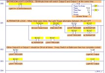
If you are trying to do the program logic, you will probably need alternator logic to switch Outputs 0 and 1 ON/OFF, as shown in the attached picture. (Set the timer to "18000" to get 30 minutes. I set it to 5 seconds for testing).

Bathroom Light Control- Recbcs.jpg
 
Last edited:
What happens when the user spends more than 30 minutes in the bath? Lights out :)

Needs motion sensors IMHO, get rid of the switch and fit smart sensors that detect people plus a day / night timer or sensor so it's not on in the daytime, unless it's a dark room of course.
 
What happens when the user spends more than 30 minutes in the bath?
Any lighting designer worthy of the name knows to put 2 sets of lights in a residential bathroom - one incandescent vanity set above the mirror and controlled by a motion sensor/timer, and a second overhead fluorescent or LED light controlled only by a wall switch.

Anyway, if Ray uses a standard 3-way light switch in combination with the PLC outputs, all a user has to do if the light goes out after 30 minutes, is flip the switch to the other position. If you are worried about finding the switch, you can buy 3-way switches with lighted handles.
 
Last edited:
When trying to retrofit in a house, you are in for some fun :). I would look into a controller using z-wave. It is a wireless standard, that uses each device as a repeater. You can get home security, thermostats, wall sockets, switches, relays, etc..

You would be able to fit a relay module with an extra switch where you currently have an existing switch. You could add motion detectors and everything.

I cannot recommend a controller, but you can do some research..

http://www.amazon.com/s/ref=nb_sb_noss_1?url=search-alias=aps&field-keywords=z-wave
 
Regardless, you will at least need an input to the PLC to execute the output. Something has to tell the PLC to actually do something. Last I am aware of, is these don't read minds.

Just my silly thoughts on this:

If you need extended time, get a Clapper for the Crapper:

Well, this didn't turn out right with the pictures. OK, I think you have to do photobucket or some other host.

Light Switch.jpg Clapper.jpg
 
Last edited:
Any lighting designer worthy of the name knows to put 2 sets of lights in a residential bathroom - one incandescent vanity set above the mirror and controlled by a motion sensor/timer, and a second overhead fluorescent or LED light controlled only by a wall switch.

Anyway, if Ray uses a standard 3-way light switch in combination with the PLC outputs, all a user has to do if the light goes out after 30 minutes, is flip the switch to the other position. If you are worried about finding the switch, you can buy 3-way switches with lighted handles.

Yes, but, that would mean getting out of the bath to flip the switch.

I would still go for motion detection as the main source for turning on, at least that way if it did time out, you would only have to wave an arm or leg or both;)

I like the plc idea, but for best results needs to go in at build time, you could wire the house for Ethernet and use switches on that, I think that's already available.
 
We have to assume that this is a student problem meant to stimulate interest, rather than a practical application of PLCs.

You can buy a motion-sensor-controlled timed light switch at any building supply store (Lowes, Home Depot) for about $20. It fits in the standard switch box so can be easily retrofitted in old homes. I have two on them in my home now, one in the main bathroom, and one in the hallway. These switches have a Off-Auto-On selector switch, and an adjustment screw to set the time that the light stays on after motion is not sensed.

For the hallway switch, I mounted it 7 feet above the floor at one end of the hallway in a new box angled about 30 degrees from vertical. That way it can detect motion anywhere in the hall. I wired that switch to work with the two existing 3-way switches. The motion switch turns the light ON, but either 3-way switch can turn it OFF. Normally I just leave the light on until the timer turns it off after 2 minutes. This is enough time to go to the kitchen for a drink of water. The hard part was fishing the wires through the existing wall and ceiling.
 
Last edited:
For relays to control the AC loads, I'd strongly recommend the GE RR-9 or its newer competitor, the Wattstopper HDR. Both of these are mechanically-held latching relays intended for building lighting control systems. They have a number of advantages over other relays/contactors and SSRs.

1) They have the same ratings as a spec-grade 20A toggle switch, including Tungsten and motor (HP) ratings, so they can be used on essentially any general-purpose lighting or receptacle circuit. Other relays may have a 20A rating, but often are more restricted in the types of loads they can handle.

2) They can be mounted in a standard 1/2" knockout in an electrical box, so mounting is simple. There's a bracket available for mounting four relays on a panel.

3) Because they're latching relays, they maintain their state across power interruptions.

4) They have separate On and Off coils, so there's no ambiguity about the action in response to a given signal, in contrast to a single-coil latching relay, where the action depends on the previous state.

5) They have isolated 24V pilot contacts for status monitoring.

I can't find the GE RR-9 data sheet online, probably because the company is marketing them mainly as part of complete lighting-control systems. But they are sold separately; in fact they appear frequently on eBay.

Here's the data on the functionally-identical Wattstopper relay: http://www.wattstopper.com/products/lighting-control-panel-systems/lighting-integrator/complete-control-level/hdr-low-voltage-relay.aspx#.VLlfhZV0x1s

Note that both relays come with a connector on the control leads. I just cut it off and crimp on extension wires.
 

Similar Topics

Such a simple, low priority issue with the Wonderware HMI, but I can't seem to stumble upon the answer without seriously digging into the manual...
Replies
8
Views
3,256
Good afternoon all I'm a bit puzzled. 19 inch AB HMI. addressed 192.168.1.22. laptop 192.168.1.10. I can see it in Linx. I can download .mer to...
Replies
3
Views
623
Hello All! First Post! What is the "Timed Out" Check Box used for on the MSG instruction in Logix5000? This check box is located under the...
Replies
2
Views
1,860
Today when an operator went to start a piece of equipment that gets infrequent use they got a bunch of time out errors. Multiple errors saying...
Replies
12
Views
5,631
Hello, I've done several migrations from SLC 5/05's to 5370 L33ER Compactlogix controllers. I've just encountered my first PID instructions with...
Replies
2
Views
1,688
Back
Top Bottom