MVI56E - MCM reading 4 bye float data from CAT engine via Modbus

mahone

Member
Join Date
Apr 2014
Location
Singapore
Posts
62
Hi to all! Need some help!

I'm reading CATERPILLAR engine data of a natural gas compressor into my
MVI56E-MCM card. The card sits in a 14 slot ControlLogix rack. My Modbus read data arrays are mapped to CAT modbus addresses.

According to the information given by CAT engineer,

1 >each engine parameter needs 2 16 bit modbus registers
2 >values are signed 32
3 >values are pre-scaled using 32 float

4 >my MCM uses 16 bit INT for one register.

MCM can read data from engine but the values are not seems accurate.

I would like to know how to combine this two registers coming from the engine and correctly interpret them to the actual engine data in respective units. Any binary conversion needed? do need to apply the scaling formulas?

thanks in advance
 
Have you tried using a copy instruction to copy the MCM data into an array of Real tags in your Contrologix processor?

In the MVI56E-MCM user manual page 77 talks about coping the data using a copy instruction.
 
@gclshortt thanks for the link. I have a look.

@electric06

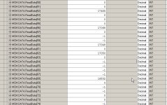
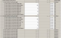
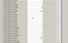
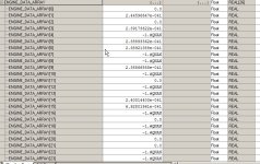
yes i have i have followed instructions given in pages 75 -80 about floating reading floating point data handling. Pls see the Real array and MCM Readdata screen capture images that i have attached here.

MCM Readdata
Real array
ModDef
port 1 command
port 1 config

Thanks.

MCM Readdata.jpg ModDef.jpg port 1 command.jpg port 1 config.jpg Real array.jpg
 
Note that in the port 1 command there is a .swap code. The order that the words & bytes transmitted by the Cat equipment may not be in the order you're expecting. The zero value in your attachment indicates you aren't swapping any bytes/words. Try experimenting with the options(1-3) until you get valid data.
 
@FluxCap

thanks for that!.

i have requested for the CAT slave device modbus config details including swap.

I will try all other swap options and see how the data change.

thanks again.
 
Also, when using the MCM module there is usually a register offset of 1. If the data you're looking for is in register pairs 40257 & 40258, you'll set up the DevAddress as 256 with a count of 2. This has caused me plenty of grief in the past.
 
In simulation i wrote swap instruction to
Word swap the final real values. I get expected values.
So either i have to use swap instruction or use word swap type for modbus swap..

Ya the device address has 1 offset,slave device address is 99 and first float register starts at 40100.
 

Similar Topics

Hi All, I just wanted to confirm something regarding this module. What I understood from the manual, is that if RS-485 mode is selected (jumper...
Replies
2
Views
361
Hi all, I wonder what's the best type of cable to use for RS-485 2 wire + GND That is, Data+, Data- & GND I know that Belden 9841 (not...
Replies
10
Views
1,067
Hey everyone, I am upgrading Modbus from MVI-56MCM to MVI56E-MCMR? Do I need to change in IO Configuration? I don't know if it is Master or...
Replies
4
Views
1,370
Hello, I am pulling my hair out trying to setup Modbus Master Read/Write Commands on a Prosoft MVI56E-MCM attached to a Clogixs 1756-L82E PLC. It...
Replies
1
Views
1,572
We have a contract to refurbish/upgrade a filling/bottling machine. We have the machine but not its control panel or PLC. We've built a new...
Replies
4
Views
3,898
Back
Top Bottom