rslogix 500 msg instruction

don2405

Member
Join Date
Jan 2014
Location
Port of Spain
Posts
33
I am new to using the rslogix 500 msg instruction, I am getting problems setting it up.
I have two a slc 5/03,s connected to ethernet via 1761- net eni, both devices seen on rs linx.

I want to have an input triggered in one plc and the output come on the other plc, after then i will try the communications monitoring (heartbeat) setup(with help from this site.

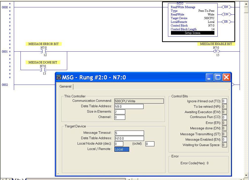
On the message instruction I configured:
Read/write: Write
Target device: 500 cpu
Control block: N7:0

SETUP SCREEN

table address: N7:0
size element: 1
channel: 0
target device
timeout: 5
table address: N7:1
Node: 0

No success, I got this message on the setup screen: no ip address configured on network.


Please, can i get some pointers?
 
Last edited:
This is an intermediate difficulty programming challenge. I have a handful of comments for you.

1. The Control Block for a MSG instruction that uses the SLC-5/03 serial port is 14 Words long. If you are planning to use N7:0 as the start of your Control Block, you need to reserve N7:0 through N7:13. Your actual data payload must use different memory addresses.

I typically do not use the same data file for my Control Blocks as for the actual data payloads, and I use separate data files for data I'm transmitting and data I expect to receive.

2. Sending an outgoing message via a 1761-NET-ENI requires you to use the DF1 Address : IP Address table inside the Net-ENI. You need to have configured the IP address of the target device equivalent to DF1 Node 0 in the Net-ENI utility or by using a configuration message inside the SLC-5/03.

Configuring the DF1:IP table is described in the 1761-UM006 user manual for the 1761-NET-ENI on page 4-6 and in Chapter 5.

3. Remember that the Net-ENI has only a small number of TCP connections it can handle; two incoming, two outgoing, and two either way. If this is the only MSG that's outgoing, you should be OK.

4. I'm not sure why you would get a message that says "No IP Address Configured On Network". RSLogix 500 doesn't know anything about IP addresses when you're using an SLC-5/03 controller, and there are only three error codes the Net-ENI can generate, none of which are specific to IP addresses. Can you describe in detail where that error message appears ?


So go ahead and set up separate areas of memory for your control block and your data payload and verify that you've configured the Net-ENI correctly on both sides, and let us know what you find.
 
"No IP Address Configured On Network".
This message appeared at the bottom of the setup screen in rslogix 500.


Thanks Ken, will read through the manual and give it another try.
 
Last edited:
Just tried it and i got this message " Target node does not respond"

can anyone post a msg instruction sample which i can use to follow?
 
This is what i did:

ENI 1 (node 1) Ip address is is used in message routing table dest 1
Eni 2 (node 0) Ip address is used in the message routing table dest 0
 
I’m not really sure what you mean in your answer.
If I understand correctly you have two SLC5/03’s each with a NET-ENI connected to them via DF1 full duplex. Each NET-ENI module has its own IP address which is what RSLinx is using to communicate with the SLC5/03’s. This appears to be working as you can see both SLC5/03’s in RSLinx (I’m assuming via an Ethernet driver in RSLinx). You need/want at least one of the SLC5/03’s to communicate with the other SLC5/03. So, let’s label each SLC5/03, the first one will be SLC_A and the other SLC_B. Attached to SLC_A is a NET-ENI (let’s call it ENI_A) with an IP address of 192.168.1.100 and attached to SLC_B is a NET-ENI (let’s call it ENI_B) with an IP address of 192.168.1.200. Now, within ENI_A you have to have the node table configured with at least one node linked to the IP address of ENI_B. So you need to configure node 1 with IP address “192.168.1.200” which is ENI_B. What this will do is link any message instruction in SLC_A that is pointed to node 1 to the IP address 192.168.1.200 which is the NET-ENI attached to SLC_B.
 
Firejo,
thanks for your response,
Yes you are correct, I did just that, but i am uncertain about the message instruction block how it works, lets say i use control block N7:0, length =14.
I want, lets say SLC A, Input I:0/1 turn on SLC B, Output O:2/0
How exactly does the table/register work and where do i assign the address in the control block 14?
Can i get some pointers or a example?

What is best practice when using MSG instruction, when is applicable to use this instruction?

Thanks
 
-- First of all I have never used the Message command with the NET - ENT so there could be a variation on the theme I am about to type. --

I will not say you cannot do it that way but normally you send integer files oven with the Message command. So with that in mind I would use the move command to move a 1 to an integer (N7:0 for instance) when I:0/1 is true. Likewise when I:0/1 is false move a 0 to N7:0.

In SLC B it would probably go to a different integer say N47:1 for instance. So if you are using the write messaging command then in the set up screen N47:1 would be your target file location.

So if everything works correctly the integer that is stored in location N7:0 on SLC A will be transferred to N47:1 on SLC B. From there you can use compare logic...if N47:1 = 1 then O:2/0 is true.

As to the best practice or when best to use the instruction I have a few thoughts/observations
1) The message command sends and receives information quickly. However the message can be delayed, degraded, or even dropped. When it is important for SLC A to know the state of an SLC B bit NOW consider the possibility of hard wiring the signal between output of one PLC and input of the other. This could cause its own set of problems for instance you might need to add a physical relay to keep the two powers separate.
2) Make sure you get the Message dn signal or message er signal before sending a new message. Sending the message without getting one of those signals - for me has proven unpridicable. This, however might not really be a concern if you send the signal once per hour.
3) The message command will allow you to send many pieces of data at once - hard to do with wires. However if you have multiple triggers for this data transfer the logic to retrigger the information can get complex. Consider having multiple message commands if there are multiple triggers.

Lets suppose you have three data triggers and therefore three message commands. The second message command fails what happens? All other message commands are in the message queue and will continue transmitting. If your logic says to trigger that message command again it will go to the back of the message queue and it will try again.

Hope this helps
 
Last edited:
So DF1 and/or EtherNet/IP message instructions in RSLogix 500 are actually pretty easy. One thing to clarify is that the word used for the message instruction (N7:0 in the example below) is not related to the data that is moved, it is simply the word used to setup and operate the message instruction (more on that later).
In the example below, the message instruction “N7:0” which is using words “0” thru “15” is a write command instruction. There are two boxes that need to be configured, “This Controller” and “Target Device” which is the controller you are messaging to (in this case where I’m doing a write message instruction”). In the “This Controller” section the “Communications Command” will be set when you first place the MSG on the rung. After that you need to tell it what word you’re going to send the data from, in this case “N9:0”, and I’m sending two words (N9:0 & N9:1). I’m using channel “0” which is always going to be the DF1 port (could be DH548). In the “Target Device” you need to tell the MSG where the data is going to in the PLC you’re messaging to. In this case it’s N10:0 and because it’s two words N10:1 will also be written to. The “Local Node Addr” is the node number of the receiving PLC. In your case, that’s where the node translation table comes in. You will have the IP address of the receiving PLC (or NET-ENI) in the “Node 0” slot of the NET-ENI connect to the PLC that is doing the messaging. So, in the below example I’m writing the data in words “N9:0” and “N9:1” from one PLC to the words “N10:0” and “N10:1” in the other PLC.
When moving inputs and outputs, I like to move them to words (N9:0 for example) and then move the words via message instructions.
In the ladder logic you’ll see the parts of the N7:0 word that are important to know. When configure a SLC you need to know that word “12” is the error bit, “13” is the done bit and “15” is the enable bit. So on rung 2, if the error or done bits go high the enable bit is unlatched which, because rung 1 is still true, will re-fire the message instruction. This is what Glen was referring to in his second “thoughts/obs…”.
One thing I will also say is that I can’t quite agree with Glen with regards to using hard inputs and outputs compared to message instructions. My 20+ years in the Industrial Automation industry is pretty much completely focused on moving data and DF1 (or EtherNet I/P) messaging is very reliable. Having said that it does rely on the medium between the two devices however if you’re close enough to hard wire you’re close enough to get an almost unbreakable connection.


SIMPLE_MESSAGE_edit_zpsjvejxdj0.jpg
 
Looking over posts to see how I could send message instructions from several SLC-500's
That all have NET-ENI's Between the SLC and a Panelview +
If I read this correctly I would address the nodes to match the IP Addresses.
If the write messages were coming from 3 of the SLC's each with there NET-ENI set up as
Node-2 & IP, Node-3 & IP, Node-4 & IP and the 4th SLC is set up as Node-1 & IP with 3 Read Messages. In the Target device box on the Write Message screen Set Up Screen would I enter a 0 and On the Read Message Target Device Set Up Screen would I enter
2-3 & 4 as I would if I were not using the NET-ENI & do I change the node addresses in the Chanel Configuration to Match the one in NET-ENI or leave them all as 1
I have only done messaging one before with the 1747 AIC THANKS
 

Similar Topics

I'm getting an Error code on my MSG instruction that I can't clear. The Error Code Number is d0. Description "No IP configured for the Network"...
Replies
0
Views
864
Is it possible to configure the MSG block (RSLogix 500 / Micrologix 1400) to have a dynamic destination IP adress?
Replies
1
Views
1,537
Hi All, this forum has been of a great help for me in learning. i have two problems 1- I have setup an alarm so i want to calculate the number...
Replies
4
Views
2,965
Hi Everyone i have attached a file below kindly have a look. so the problem i am facing here whenever the binary bit B3 goes on it goes into...
Replies
7
Views
2,496
Hi All, I am new to plc programming. I have created a ladder logic in rslogix 500. Now I want to give input at one plc and get the output on the...
Replies
16
Views
11,108
Back
Top Bottom