PLC wiring questions

arad

Member
Join Date
Mar 2015
Location
au
Posts
11
Hi guys,

I just received my first Siemens S7-1200 PLC and I am struggling on understanding the wiring diagram.

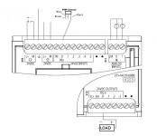
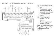
I have uploaded a diagram(wiring2.jpg) which I am trying to connect all the components together, however, I just couldn't connect them all.

1. What do I connect the ground to?
2. What does the "Digit" before the L+/M mean?
3. Does the X12 output supply power or I have to connect the 24V output from the Input part?
4. For the PNP sensor, I am confused what blue wire connects to. Does it connect to M or 1M?

Any help will be greatly appreciated as this is my first time "touching" wiring.

Thanks in advance.
wiring.jpg wiring2.jpg
 
1. Connect ground to 3rd left top terminal with ground/earth symbol or ground the -ve side of 24vdc
2. See above ^ (edit... 1M, 2M, 3M... separate M terminals)
3. Put your own 24vdc to 3L+ and 3M with -ve of loads connected to 3M
4. Blue to M. Link M to 1M if you are using PNP switching sensors
 
Last edited:
1. Connect ground to 3rd left top terminal with ground/earth symbol or ground the -ve side of 24vdc
2. See above ^ (edit... 1M, 2M, 3M... separate M terminals)
3. Put your own 24vdc to 3L+ and 3M with -ve of loads connected to 3M
4. Blue to M. Link M to 1M if you are using PNP switching sensors

1. My power supply doesn't have a 24V ground pin. So I simply connect pin3 back to pin2((M)?
2. Do you mean the digit is only for labeling purpose?
3. got it. That means the -ve of the power source connects to both 3M and -ve of the load.
4. Why can't it use the power source from the input part?

Thanks
 
No experience on the Siemans S7 but...
1. Ground should be connected to the third terminal from the left on the X10 terminal strip (between the two sets of L+/M terminals). Did this answer question 2 also? If not, I didn't see any digits on either diagram.
3. Your two diagrams differ on this part. I would suggest hooking up the power supply to X10 as shown and see if you end up with 24 vdc across 3L+ and 3M. If you don't, you probably need to hook up a separate power supply as shown in wiring.jpg. You could to program an output to energize and see if you get 24 vdc at that particular output.
4. It looks like it could hook up to either. Since 1M appears to be affiliated with the inputs, I would hook it up to 1M and hook the brown up to +24 vdc.

Hope this helps.
 
Probably "Leiter" or conductor, in German the 3-Phases 230V/400V are "Aussenleiter" L1/L2/L3 and neutral is "Neutralleiter", L+ is the positive "Leiter" in DC. But I think the L actually comes from English "line conductor", at least according to the German wikipedia article.
 

Similar Topics

I'm currently working on a PLC setup and could use some advice on the best way to manage my power supply units (PSUs). Here's the configuration...
Replies
3
Views
355
I need one PLC to receive a signal from another PLC. Can I wire the PLC output of one PLC to the input of another PLC? (same voltage of...
Replies
15
Views
3,734
I'm a beginner and not sure what to do. I want to monitor the rotation of a motor. I have a FX3U PLC and a RI58-O/100 encoder available. The...
Replies
2
Views
1,352
Hello friends. I am new in this forum. Can somebody help me by giving S7 300 PLC wiring technique pdf? Specially how to power up the CPU and I/O...
Replies
1
Views
1,173
Hi, On a previous thread I asked about how to connect a float switch to a PLC. http://www.plctalk.net/qanda/showthread.php?t=126829 As I'm a...
Replies
18
Views
5,481
Back
Top Bottom