PLC-5/15 Woes

Mad_Poet

Member
Join Date
Feb 2017
Location
Virginia
Posts
375
Dear Sirs,
I have a PLC-5/15 set up in a rack with I/O and I can not 'see' the inputs on the input cards, nor can I light up the outputs.

The Rack is a 1771-A2B - eight slot chassis.
My input cards are 1771 IVN (32 bit DC) and an 1771 IBN (also 32 bit DC).
My output card is a 1771 OVN (32 bit DC).

Should my PLC-5/15 be in 'scanner' mode or 'adapter mode'?

The switches in the backplane are set to load the PLC from the EEPROM on power up. (I have no battery in the PLC.) Do I need to use 1/2 slot, 1 slot, or two slot addressing?

I am using RSLogix 5 to program it and I can write baby ladder logic programs and I'm pretty sure I am downloading them into the processor. (I can go online and offline and upload the program from EEPROM into the laptop.) I use RSLinx and a PCMK card with cable to access the PLC.

I think I configured the rack and the I/O cards. When I force an input or an output the rack configuration, module display, shows the bits changed.

But I can not see the bits change when I toggle an input to the input card, nor can I get the output bit LED to light up on the output module.
Help?
Mad_Poet.
 
The "adapter" and "scanner" settings refer to the integrated DH+/RIO port.
It is irrelevant for the I/O in the central chassis (with the CPU). The most typical is either set to "DH+ Link" or "scanner".

The 32-channel cards require ½-slot adressing, or 1-slot adressing with input modules and output modules alternating (because 2 neighbouring slots share the input and output image).
 
Welcome to the forum, Mad_Poet.

You picked an interesting PLC with which to start your programming...
I am a bit concerned that you are trying to run this PLC without understanding the basics of the hardware.

The manuals for the hardware should still be available from Rockwell.

The dip switches on your chassis and on your PLC need to be set correctly for what you have.

If I remember correctly:
1/2 slot addressing gives you 32 channels per physical slot
1 slot addressing gives you 16 channels per physical slot
2 slot addressing gives you 8 channels per physical slot

From that you can determine your physical I/O addressing for the program.

From a safety viewpoint, make sure you see your inputs before you start playing with outputs. You may get an incorrect operation if you force the wrong output.
 
Well, the rack and slot addressing for PLC5 is a bit confusing the first time.
And the ½-slot, 1-slot and 2-slot terms are really confusing.
In AB Lingo, a "rack" is 8 input words plus 8 output words. Whereas a "chassis" is a physical rack, which in turn may contain part of a "rack", a full "rack", or several "racks".
And "½-slot" means that a half physical slot is assigned to a full "imaginary" slot (1 word), which is to say that a full physical slot is really assigned 2+2 I/O words.
Simple when you have got the hang of it, right ?
Someone must have had a long visit to the local bar before he came up with the above for describing the assignment of the I/O image to the physical I/O in a PLC5.

Apart from that, an old PLC5 is OK for learning basic PLC programming.
But I would look into learning programming something that supports IEC61131-3 languages.
 
getting started - down and dirty ...

assuming that all of your outputs are "SAFE" to be turned on ...

put the processor in RUN or REMOTE RUN mode (PROC LED should be green) ...

go through the OUTPUT table and start manually putting ONES in the boxes ... (no you do NOT need "code/ladders" to do this) ...

watch the LEDs on the output modules ... get excited when any LED comes on ... keep going - looking for a pattern of how the output bit/boxes line up with the LEDs/screws on the output modules ...

NOTE: this is a "classic" model PLC-5 ... that means that the INPUT bit/boxes will not change status unless the processor is in the RUN or REMOTE RUN mode ...

once you've seen some "output" action - then start turning on some of your input terminals - while watching the bit/boxes on the INPUT IMAGE TABLE ... note that the LEDs on the input modules should light up if you have the wiring correct ...

going further ...

tell us which modules you have in which slots ... TIP: "letter" the slots in your description ... example: processor in slot A ... 1771-IBN module in slot B ... etc.

incidentally - setting up the IO Configuration screens is pretty much a waste of time with the PLC-5 family ... specifically, you don't need to do this to get the digital I/O modules to work ...

TIP: look on the SWITCHES tab of the Processor Status feature ... tell us what the Local I/O addressing mode is set for ... if it's set for TWO_SLOT then you'll have to change it ... that mode won't work with your 32-point modules ...

MOST IMPORTANT: have fun ... if you're not having fun then you're doing it wrong ...
 
Last edited:
Many Thanks, all.
John, Looks like 1/2 slot addressing is what I should be using.

Ummm. Right now the rack and cards is sitting on a desk with nothing else actually attached to it. I do have a 'box' with lights and switches which was wired to the I/O for testing. In frustration I disconnected it, and started using jumper wires to check all the Inputs on the modules.

Ron, just where do I find this 'input image table'?
(In the configuration, I configured the rack and I can 'see' the modules I programmed into it . . . but I don't see where my configuration translates to the actual modules.) {And, yes, I know that I have to have the processor in Rum or Remote Run mode while monitoring the logic to 'see' the bits.}

The PLC is in the slot for the PLC. Slot zero, to the right of the PLC, is where I put the 1771 IVN input module, and slot one had the 1771 OVN output module. I think it was slot six had the 1771 IBN input module and slot seven contains the power supply. I also have an external 24 Vdc supply supplying power to the I/O modules. (My inputs do not light up without it.)

Just so you know, we have another PLC-5/15 running a 'live machine'. In service maybe twenty years now . . . runs great. But, if it dies I might be tasked with replacing it and in doing my homework I learned that I had best be at least semi-capable with the PLC-5 before I tackle it.
Thanks,
Mad_Poet.
 
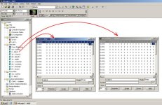
double-click to access the Input and the Output Image tables - (the bit/boxes) ...

The PLC is in the slot for the PLC. Slot zero, to the right of the PLC, is where I put the 1771 IVN input module, and slot one had the 1771 OVN output module. I think it was slot six had the 1771 IBN input module and slot seven contains the power supply.

incidentally - you're still using NUMBERS - and not "letters" as I requested ... the problem with using NUMBERS to describe your module positions is that those numbers can CHANGE based on how you have the chassis DIP switches set ... we cannot tell you exactly how to answer your questions in DETAIL unless we have DETAILED information from you ...

NOTE: in a PLC-5 system - the addressing revolves around "Racks" and "Module Groups" - not "slots" ... this can be very confusing - even to folks who have quite a bit of experience with these systems ...

I'm offline now for most of the rest of the day - but I'm sure that other members can help you out ... good luck with it ...
.

plc5.jpg
 
Last edited:
Ron, just where do I find this 'input image table'?
(In the configuration, I configured the rack and I can 'see' the modules I programmed into it . . . but I don't see where my configuration translates to the actual modules.)
It is defined by chassis switch settings.
The configuration in RSLogix5 is for your own information only, it does not affect the actual PLC configuration (so it is an error source if you update the hardware without the software, or vice-versa).
You have to set the DIP-switch in the chassis for ½-slot adressing. The 1st "rack" in the central chassis starts from 0. So the first input on the first card has address I:0/0, and the last input on the first card has address I:1/17 (octal !).

There is also a jumper for selecting if the chassis uses the power supply in the chassis or an external.
The manual says "Important. You cannot power a single I/O chassis with both a power supply module and an external power supply". So you have to decide which one you want to use.
 
Success !

Dear Ron,
Many Many Thanks.
It was the half rack setting on the dip switches.
(Or maybe when I set the switch to not load off the EEPROM.)

That Switches tab of the Processor Status - that was set for two slots. Right after changing that to half slots the outputs started working.

It was after that that I found what you point out so well with that picture - where to 'see' the I/O points. From there I saw my inputs change as I jumped the inputs.

I sense some irritation that I used 'numbers' instead of 'alphabet characters' to describe which slot the cards were in. I'm sorry, but I can't see any difference between describing the slot as 'slot to the right of the PLC' or 'slot 0' or 'slot B'.

But it's all good now. I have two switches and two lights wired in. I have two lines in the ladder logic. Input I:000/0 and Input I:000/2 go green when I push the buttons and my outputs at O:2/1 and O:2/11 light up along with yellow and green lights in my box.

I am now very pleased with myself.
Mad_Poet.
 
I sense some irritation that I used 'numbers' instead of 'alphabet characters' to describe which slot the cards were in. I'm sorry, but I can't see any difference between describing the slot as 'slot to the right of the PLC' or 'slot 0' or 'slot B'.

I'm sorry that you misunderstood – I wasn't irritated ... I was simply trying to be as helpful as possible – and it's just that it's easier to help people solve their problems "sight-unseen" when there is absolutely no ambiguity involved in discussing how the system is put together ...

in a prior lifetime, I spent about eight years as the "telephone answer man" at an Allen-Bradley distributor ... helping frustrated customers over the phone is "challenging" at best ... when it came to addressing problems, much of the customer's confusion was often (usually?) related to mis-counting the "slots" in the chassis ...

for example: a technician who was perfectly familiar with the SLC-500 hardware would correctly count the processor's slot as "0" – the next slot as "1" and then so on – sequentially and in decimal ... 0-1-2-3-4-5-6-7-8-9-10 and so on ...

the PLC-5 system doesn't work the same way ... first of all, the I/O addressing uses OCTAL numbering - not DECIMAL ... and the processor's slot doesn't get counted ... and technically speaking, the term "slot" (as part of the module's address) usually only comes into play for something like an analog module being used in a two-slot addressing mode ... (this is often specified as the "Module" entry on a Block Transfer instruction in the ladder code) ... (this would always be either a "0" or a "1" entry) ...

so ... with the PLC-5 processor located in SLOT A ... then ...

SLOT B - (the next slot/location after the processor) might contain:

Module Group 0 ... or ...
Module Groups 0 and 1 ... depending on how the "addressing mode" DIP switches are set – and on what type of module is being inserted ...

and ...

SLOT C - (the second slot after the processor) might contain:

Module Group 0 ...
Module Group 1 ... or ...
Module Groups 0 and 1 ... or ...
Module Groups 2 and 3 ...

depending on how the "addressing mode" DIP switches are set – and on what type of module is being inserted ...

going further ... now that you have half-slot addressing selected – then you have TWO "logical" racks – within the ONE "physical" rack (or in the ONE "chassis" as it is more accurately called) ...

anyway ...

the point that I'm trying to make is that there's plenty of room for confusion here ...

so ...

when discussing this type of stuff over the phone - I learned early on to have the troubled technician on the other end of the phone line just "letter" all of the slots from the left to the right A-B-C-D-E-F-G-etc. ... then we could discuss exactly WHAT module was being inserted WHERE – without anything ambiguous going on ... a simple "failure to communicate" could easily occupy hours of frustration – there's really no need for that ...

so ...

glad you got it working ... all is well ...

peace ...
 
Last edited:
Dear Ron,
Many thanks again. I hear you on how confusion can cause problems.

Once you pointed out that Inputs and Outputs are under 'Data Files' . . . and I got the half slot dip switch set correctly everything fell into place.

Looking at the Inputs as I jumped them, and seeing them change states, I realized quickly how my inputs went I:0/0 through I:0/17 (octal) for the first half of my first input module. Then I:1/0 through I:1/17 for the second half. And, of course, that is why my outputs went from O:2/0 etc. etc. to O:3/17.

I have a little tutorial on PLC-5/15 programming I found. Now I can get moving with it.

Thanks again,
Mad_Poet.
 
FYI - about that 'load from EEPROM' Dip switch

I'm making good progress with the tutorial - parallel and series circuits in the ladder. And a timer.

But, Just so I'd know, I tried setting the dip switch on the chassis to load the PLC from the EEPROM, and I could not access the PLC from the laptop at all. I think the half rack addressing might have something to do with it as I'm pretty sure with '2 rack' I was able to access the PLC.

There is no battery in my PLC.
So, when I power it up with the dip switch set to not load the PLC from the EEPROM the PLC comes up with a red PROC light. I download my program into the PLC and the PROC light goes out. Then I put it in Run mode and the PROC light turns green and everything works as expected.

Mad Poet.
 
Dear John,
There is an EEPROM installed. It used to contain a copy of the live machines program. Now it has a copy of the last program I made.

I have no battery in my PLC, which is why I was trying to run it with dip switch 6 set to load off the EEPROM - that way it would come up running.

When I set the switches from '2 rack' to 'half rack' I also flipped dip 6 so it would not load off the EEPROM.

I had also set up a checkerboard type pattern of turned on bits in the 'Force Output' table. When I powered everything back up and loaded my program into the PLC . . . The PROC light turned green and all kinds of little red lights lit up on my output module.

THAT was a VERY good feeling.

Anyway, time for me to go home.
Thanks again for all the help guys.
Mad Poet.
 

Similar Topics

I have a problem with PLC 5/250 PI. Two (dual reduandant) data concentrators have recently been "locking up" and showing red light on the...
Replies
3
Views
2,134
The past week we received a new piece of equipment from Germany which utilizes siemens controls. Typically in our company we use A.B. controls for...
Replies
6
Views
115
the conveyor can stop because of a safety sensor or safety switch. And also it can stop because of an object jam detector sensor. If the conveyor...
Replies
5
Views
166
Good Day to all of you, this is my first post, i will try to explain as best as possible, english is not my natural language. I am performing an...
Replies
0
Views
36
Hi All, Someone at work has put a PLC system on my desk, that's just been taken off an idle production line. He said "It's an S7 PLC. We don't...
Replies
10
Views
230
Back
Top Bottom