You are not registered yet. Please click here to register!


plc storereviewsdownloads
This board is for PLC Related Q&A ONLY. Please DON'T use it for advertising, etc.
 
Try our online PLC Simulator- FREE.  Click here now to try it.

New Here? Please read this important info!!!


Go Back   PLCS.net - Interactive Q & A > PLCS.net - Interactive Q & A > LIVE PLC Questions And Answers

Reply
 
Thread Tools Display Modes
Old March 17th, 2023, 11:17 AM   #1
Aljubovic
Member
United States

Aljubovic is offline
 
Join Date: Jan 2023
Location: Louisville, Ky
Posts: 72
Can a helpful soul double check this click program for bugs?

Hello. I have been working on my first plc project for a while now. I just ordered all the parts that I need and before I did that, I created the program in do-more designer and simulated it. After debugging it the best I could and everything in the simulation worked, I transferred it all over to the click programming software so when my plc arrives, I can quickly start testing it.
This program is used to make an automated hydrostatic pressure testing unit for industrial hoses and has 4 devices.
1. pressure transmitter, 4-20mA, 0-2000psi
2. 3/2 Solenoid valve (for air supply cut off)
3. hydraulic solenoid valve (when overpressure detected, this will open and relief water pressure in hose)
4. ip current to pneumatic transducer, 4-20mA, 3-120psig

How it works is an operator will connect a hose to the system, then they will type in a pressure setpoint at which the hose will be tested at and also a time for how long to be held at that pressure. It does this by outputting the proper psi in the ip transducer to get the correct pressure output (Let's say the setpoint is 1000psi, the transducer would have to drive the pump with around 60-64 psi. The exact amount is calculated and then the ip transducer slowly ramps up to that pressure and holds it for the duration of the test. In this program the fluid supply valve and the pressure relief valve are manual, so when the operator presses the start button, a message appears on screen, they first need to open the fluid supply valve and wait for the hose to fill up with water, once water comes out the end of the hose (no more air inside the hose) the operator will close the relief valve, then they will press the okay button on the message that appeared on the hmi.
When the pressure test is done a message appears on screen to close the fluid supply valve and open the relief valve on the hose. Pressure will start dropping to 0 and then the program will reset.

If you want to actually simulate the program you will need to open data view in do-more and add in all pushbuttons, messages and setpoints to see what the program is doing. There are too many messages and outputs that I do not expect for anyone here to understand how this program fully works.

The do-more designer program has comments on most of the rungs to show what each one does.
Let me know if anyone finds any bugs, or rungs that will not work in my program for some reason.

Any help is appreciated. I will post the program for do-more and click down below.


Edit: There are more devices like hmi and mechanical devices, but I just put the main input and output devices. I will be using a c-more EA9-T6CL-R hmi.

Last edited by Aljubovic; March 17th, 2023 at 12:03 PM.
  Reply With Quote
Old March 17th, 2023, 11:27 AM   #2
Aljubovic
Member
United States

Aljubovic is offline
 
Join Date: Jan 2023
Location: Louisville, Ky
Posts: 72
Here are the programs
Attached Files
File Type: zip Hydrostatic pressure programs.zip (28.4 KB, 12 views)
  Reply With Quote
Old March 17th, 2023, 12:23 PM   #3
parky
Member
United Kingdom

parky is online now
 
parky's Avatar
 
Join Date: Oct 2004
Location: Midlands
Posts: 4,790
Not run it but a quick look there are a few comments, I agree with splitting programs but I think you have gone too far.
First of all, a call to first scan, why not just put that in the main routine, the seperate call to the timers this makes things harder for others & possibly you, your monitoring the main program & a rung with a timer contact is not going true, so you have to go to the program with timers to see what's happening.
I do agree with seperate I/O mapping as this makes it easier to simulate as is the simulation program, Get rid of most of the NOP's it make sit look messy.
perhaps leave a couple as I know the editor is awful & just inserting lines seems very poor.
You seem to be copying data from one register to another many times it is difficult to follow.
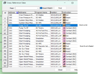
I noticed C63 "Start Pumping" only seems to be reset on a Reset PB, Is this correct ?. what about normal end of the process ?.
No comments on some rungs so it would help a little more to add a bit more detail.
You also have a load of reset coils without them being set, also noticed a couple where you have an OUT coil but also reset of that coil, it should not need it, for example if you have logic that turns on a coil (not reset) then adding a reset will only reset it until the next scan because the logic is true so turns it on again, on the same issue, if the logic driving the coil is false then no need for reset.
I think a lot of your problems are because the amount of programs you have split it into, it has become so fragmented that you have lost your way a bit.
  Reply With Quote
Old March 17th, 2023, 01:28 PM   #4
Aljubovic
Member
United States

Aljubovic is offline
 
Join Date: Jan 2023
Location: Louisville, Ky
Posts: 72
@parky Yes I should put the first scan into the main routine, but all other subroutines have a purpose and I can understand what each program is doing. Everything is very disorganized but it all works if you simulate it. I am just very worried about testing it in the real world because of accuracy and small errors that might arise.


The start pumping and many other timers, messages, and outputs are all reset with a reset pb. If ANY message appears on the screen the operator has to acknowledge it first and then hit the OK button on the message. This applies to every single message that will be displayed on the hmi (except 2 messages). Whenever the program is started, it will always end on some message display. This can be an error message, overpressure message, test passed message, and so on. Every single message has an OK button and it will reset the whole system back to 0. For the normal end of the process either a test passed or failed message will be displayed, when the operator presses OK the system will be reset to state 0 and everything else will be reset too.


Most of the reset coils are all for the messages and pushbuttons, I tested this program a month simulating it in do-more and everything worked properly. The system reset button is used to reset any messages, outputs, pb at the end of a test or when something goes wrong.


Since I am using a manual fluid supply valve and manual relief valve for when nothing goes wrong I have to display a message every time the system is ready to start the test and for when the system is ready to depressurize. So when the operator presses the start button a message is displayed to follow these steps (open relief valve, open fluid supply, wait for water to come out, close relief valve, and once completed he will push the ok button on the hmi. There are rungs that are always on that check if the system is building pressure and also a max pump to sp time, so if the operator does not do this and the system does not build pressure it will display an timeout message and the system will HAVE to be reset using the system_reset_pb


I understand that the program is very disorganized and there is a lot to look at, but running the simulation has given me good answers. I just hope that it will work using the real devices.


What rung did you see a load of reset coils without them being set?


Also I thought that with each scan that each subroutine was checked? All of my timers in do-more worked as the program went through each step. Not sure what you mean by this "your monitoring the main program & a rung with a timer contact is not going true, so you have to go to the program with timers to see what's happening" because all of the timers in do-more worked as I ran the simulation.

Are you saying that my timers wont be scanned if another subroutine is being scanned?

because the timers work at all points in the program if you simulate it the click is almost an exact copy of the do-more program so I think it will work the same too


Anyway there is too much for me to explain and because this is my first program it is very disorganized. My best bet would be to wait for the parts to arrive and slowly test each one.
  Reply With Quote
Old March 17th, 2023, 02:08 PM   #5
parky
Member
United Kingdom

parky is online now
 
parky's Avatar
 
Join Date: Oct 2004
Location: Midlands
Posts: 4,790
The HMI program, as for testing I cannot as I do not have the HMI program so very difficult to run it.
see screenshot regarding the two I found without really looking.
Attached Images
File Type: png Xref.png (211.3 KB, 105 views)
  Reply With Quote
Old March 17th, 2023, 02:29 PM   #6
Aljubovic
Member
United States

Aljubovic is offline
 
Join Date: Jan 2023
Location: Louisville, Ky
Posts: 72
@parky
Oh, thank you for noticing that. I copied (or at least tried to copy) the entire program that I made in do-more into the click program. I guess I missed something very important, the system would have not started pumping to sp at all if this one set command is missing.

A set command for start pumping is supposed to be in 20 states, rung 6, once on step 40 and psi has not dropped after starting the pump, pump_to_sp is set which starts a timer, that timer sets on ready_to_pump in 40 pretest pressure rung 1 which turns on start pumping. Start pumping is connected to 40 pretest pressure rung 4 and 5, which ramps the current to pneumatic transducer up to sp.

Now that I realize it I don't even need rung 1 (the start pumping output), it is just an extra command. I could just put ready_to_pump on 40 pretest pressure rung 4 and 5 instead.

Thanks for making me realize a crucial mistake in the program.


Also, I forgot to delete the Air out timer. This was used when I had a solenoid operated fluid supply valve, now that I have a manual one this is not used anymore.

Last edited by Aljubovic; March 17th, 2023 at 03:11 PM.
  Reply With Quote
Old March 19th, 2023, 03:38 AM   #7
parky
Member
United Kingdom

parky is online now
 
parky's Avatar
 
Join Date: Oct 2004
Location: Midlands
Posts: 4,790
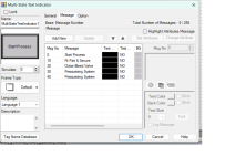
As you seem to be having some Manual intervention one suggestion is that rather than setting bits for displaying messages on the screen use the multistate text indicator, set it as an integer rather than bits, add the messages giving each message a number based on the Sequence variable, this way it will automatically display the text for each sequnce.
For example:

When sequence =
0 "System IDLE"
10 "Fit Test piece & Acknowledge"
20 "Pressurising System"
30 "........
40 "......
& so on.
This way although you may have extra steps it is a way of showing the current state & giving the operator instructions on what to do.
Even if some steps you do not need to change the text just repeat it for the sequence number.
This means you do not have to set/reset bits it works off the sequence number.
Attached Images
File Type: png Multistate.png (117.2 KB, 77 views)
  Reply With Quote
Old March 20th, 2023, 06:24 PM   #8
juddge
Lifetime Supporting Member
Australia

juddge is offline
 
Join Date: Oct 2021
Location: Penrith NSW
Posts: 11
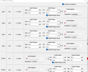
one thing i did notice in the program is a alot of math for analog

the click plcs have the analog inputs alrady scaled


example - 4-20ma input scaled to -30 - 50 Celcius - the plc internally does that math for you when settings up the input you add the scaling and its done for you already
Attached Images
File Type: png Screenshot 2023-03-21 092651.png (42.9 KB, 50 views)

Last edited by juddge; March 20th, 2023 at 06:27 PM.
  Reply With Quote
Old March 21st, 2023, 03:05 AM   #9
parky
Member
United Kingdom

parky is online now
 
parky's Avatar
 
Join Date: Oct 2004
Location: Midlands
Posts: 4,790
@Juddge: yes, but there has been a lot of input from other posters on a previous post on this system, like most of us we all have our way of doing things, & some have indicated that by scaling with the use of perhaps the HMI on a setup or engineering page means it is easy to re-calibrate sensors rather than have to change the fixed factors in the PLC, I sort of agree in this case it is probably not worth it as less than a couple of sensors seems a little pointless, could be a problem with people messing with it without a proper understanding we all know it is not long before operators find the engineering password.
The OP is still on a learning curve & it gives them ideas, however, sometimes these ideas are taken to the extreme. I hope the OP reads all the posts & makes his own judgement on what is nice to have & what is practical which will depend on the application.
  Reply With Quote
Reply
Jump to Live PLC Question and Answer Forum


Currently Active Users Viewing This Thread: 1 (0 members and 1 guests)
 
Thread Tools
Display Modes

Posting Rules
You may not post new threads
You may not post replies
You may not post attachments
You may not edit your posts

BB code is On
Smilies are On
[IMG] code is On
HTML code is Off

Forum Jump

Similar Topics
Thread Thread Starter Forum Replies Last Post
Subroutine philosophy Doug-P LIVE PLC Questions And Answers 31 February 11th, 2013 07:40 AM
when i double click dslaunch or csmain- nothing happens brucewoodrem LIVE PLC Questions And Answers 3 August 17th, 2009 01:04 PM
How to check if the PLC & its program are working fine? flyers LIVE PLC Questions And Answers 7 March 27th, 2008 09:45 AM
Questions abt Siemens S7 200 Preeya LIVE PLC Questions And Answers 3 April 9th, 2007 08:39 AM
S7 Program execution RMA LIVE PLC Questions And Answers 4 May 19th, 2005 07:11 AM


All times are GMT -4. The time now is 06:59 AM.


.