PID forms

jjnelson81

Member
Join Date
Apr 2007
Location
Springfield, MO
Posts
32
Well lets try this again. I wrote a long post and my browser crapped out on me.

I am looking to write my own PID equations into my PLCs. I work for an OEM that uses any PLC that is specified. I want to eventually write an auto-tune routine for out process but needed a standard PID loop to get that down. I know everyone is aware that each PLC mfg uses a little bit different form of PID controls. This does not make it easy to have a piece of standard equipment (less the PLC) and use the same logic for auto-tuning the PID. Here are some equations:

593410d9db33a7cc59b581aca4a11565.png


6dbbb7aafc289a41c2345438e0814ab2.png


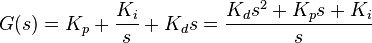
Here are 2 equations, the first being a pretty standard PID equation and the second being the Laplace Transmform form of the same equation. It looked to me that the Laplace form would be easier to implement with the math functions available in a PLC. Here is my stumbling block.

What is the "s" variable in the second equation? I think it is a function of time but don't know how to get it. Do I need to run some timers and sample the error over time?

Any help would be great. I have scouered the internet for the last week reading and learning, I know what each portion of the equation is supposed to do, how do I make my own?
 
Since you don't even understand the s-domain, I'm pretty sure it'll be quicker, cheaper, and easier if you purchase software that is already made for this purpose. Several companies produce autotuning software that can work with a variety of PLC brands.
 
Since you don't even understand the s-domain, I'm pretty sure it'll be quicker, cheaper, and easier if you purchase software that is already made for this purpose. Several companies produce autotuning software that can work with a variety of PLC brands.


Last time I checked, this forum was for posting question and getting some direction on how to solve said questions, not get ridiculed for what one does not know.

I understand that the s-domain is a function of time... a complex number which, in the Laplace transform equations is unitless. I am trying to grasp this concept and apply it to my application, that utilizes a cascade control loop to control variables of flow and dissolved oxygen via a flow control valve.

I am well aware of how to tune a PID loop using several different proven methods such as the Ziegler-Nichols method and also that there are several auto-tune softwares available. I am also aware that several PLC mfgs offer built in auto-tune functions (such as AB CLX).

I asked how I would implement a PID equation with logic.
 
I'm afraid there's a pretty big leap between the first and second equations. The s-domain is not a function of time. It is an imaginary number without time in it at all. In practice, s = j*w, where j is of course sqrt(-1) and w is the frequency of the source in radians per second. In other words, in your second equation, you can see that different parts of the PID output respond differently at different frequencies. At high frequencies the integral output will drop and the derivative output will rise, and vice versa.

What kinds of PLC's are you using? Anything where you are stuck with ladder logic would be a huge pain in either domain. If you have a PLC with text-based programming capabilities and are comfortable with them, then yes, the s-domain would be the way to go. But I would highly reccommend buying a text book on LaPlace and Fourier transforms, as well as the frequency domain, before just diving into it. It's not intuitive to most people to think outside of the time domain.
 
I second the others

I agree with the other's assessments. Learning frequency domain techniques and their conversions back into time domain is generally a whole subject of at least 1 class in an engineering curriculum. Further, the time invested to develop this code has essentially already been done by the various PLC manufacturers, which is why most of all have PID instructions to work with. While I certainly don't want to discourage anyone from expanding their knowledge, from a productivity standpoint, I think you would be ahead by learning the exact differences between manufacturer's algorithms, and writing your own autotune logic for each, if you so desire. I think you will find that the actual variety of the algorithms are not that great in quantity. Finally, there are some 3rd party software programs that are VERY good at analyzing loop step responses and the like, and yielding suggested gain values, corresponding graphs, and frequency domain equations linked to the values selected. Should you still choose to pursue writing your own PID logic, I wish you luck, and would like to review your results, as it sounds like a fun side project.
 
A PID is a PID is a PID .... NOT.

You didn't say which form of PID you wanted or what you are going to do with it. Various forms work better than others in certain applications. I didn't want to post 6 different forms of PID.

The rest of you should learn about Tustin's approximation for s. This allows one to convert functions in the s domain to the z domain. s=(2/T)*((z-1)/(z+1))

Matched Z Transforms, MZT, are better but much harder to convert.

In the end you will find the two equations are just different ways of saying the same thing so one can ignore the second equation and concentrate on the first.

Here is the first equation translated into simple discrete equations
COi(n)=COi(n-1)+Ki*T*Error(n);
CO(n)=COi(n)+Kp*Error(n)+(Kd/T)*(Error(n)-Error(n-1))
Where
COi is the integrator's contribution to the control output
CO is the total control output
T is the sample time

That is simple.
 
I'm afraid there's a pretty big leap between the first and second equations. The s-domain is not a function of time. It is an imaginary number without time in it at all. In practice, s = j*w, where j is of course sqrt(-1) and w is the frequency of the source in radians per second.

Reading this, I see some contradiction. First, you state that it is not a function of time, and then the imaginary number contains a frequency (which is time based) portion in radians/SECOND.

My initial thoughts for the derivative portion, in a simplified way would be to take Kd and multiply it by (error - past error) to get a suedo feedback loop from the process response. So if I use a negative Kd and a positve Kp, then the CV out of the equation would start to "brake" itself as it approached the setpoint.

So I would have a crude PD controller. I am not sure if I will need the I portion yet or not.
 
Yes, Yes, Yes

That rocks! I was posting a simple response when you replied to my thread. It looks like your derivative portion in similar to what I was thinking would work. I don't know what equation will work best for my application yet.

Thanks for a productive answer.

PS - I like your USSA reference, sad isn't it?!
 
Originally posted by jjnelson81:

Reading this, I see some contradiction. First, you state that it is not a function of time, and then the imaginary number contains a frequency (which is time based) portion in radians/SECOND.

Generally speaking, when someone refers to a function as time based it is the time that is the important quantity. That is, all other things being equal and non-zero, the output is different at time 0, time 0.1, time 1, time 10 and time 100. With frequency domain equation the output at all those times would be the same as long as the frequency doesn't change. Just because time is a minor basis doesn't make the value time based. As Peter said you will want to work in the time domain in the plc.

Peter gave you the easy part of your request. I write my own PID equations in a plc quite often. I don't like the baggage that many of the internal ones bring along. Peter provided you with the independent positional form of the equation with all elements acting on error. As he said, this may not be the best fit for what you want to do. It all depends on your system, which in your case sounds like a single system. Also, keep in mind that Peter's equations don't contain any integral limiting, absolute output limiting or intergral preload. You need to put the tidy wrapper around the equation.

The second part of your request is where you will really need to do some research. As you said, there are several tuning correlations out there once you have the plant parameters. As an asisde, I'm not a big Z-N guy but that is another story. The plant parameters are often determined manually by looking at a graph of a step response. the human brain is very good at picking important trends out of visual representations. Pulling those plant parameters out of a noisy input signal in a plc can be a challenge. The plc can't 'look' at the data like you can and pick out the trends. You will have to code it to do that.

Go get 'em, tiger.
 
That is why you should let us know what the application is. Some of us have a lot of experience control loop control with MANY DIFFERENT kinds of systems.

Here it goes:

We use the PID loops in a cascade control function for biological nutrient removal. A dissolved oxygen analyzer is the input to the first PID. This PID output generates a flow setpoint in SCFM to control a second PID loop that then controls the flow control valve position.

The challenge in this system is the delay that the dissolved oxygen variable has, along with the other system disturbances of bological oxygen demand, temperature, pressure and age of the micro-organisms.

So you can be truckin' along and then an outside variable could send your dissolved oxygen whirling in a downward spiral. The system responds and takes time to recover. During the recovery process another variable could change causing the dissolved oxygen to spike (which you are trying to drive it up from the last drop) and cause it to sky rocket. Conventional PID loops dont like this much disturbance, hence the reason we are adding other variables into the mix to help predict and auto-tune on the fly.

We use siemens, GE, modicon, AB processors from all eras (PLC 5, SLC, CLX, 90/30, Rx3i, quantum, premium, etc.)
This is the reason for wanting to write our own PID equations into the ladder (or FBD) logic. So we can repeat the same tuning parameters across the board and they do the same thing in each controller. Instead of parallel equations in one, series in another, standard vs. ideal and so on.
 
You first PID formula is best used for fast system when time constants are in the milliseconds. Normally process people use the ISA form

Gc(s)=Kc*(1+1/(Ti*s)+Td*s)

Notice that now there is 1 controller gain and a integrator time constant, Ti, and a derivative time constant, Td.

Often times the derivative gain works only the rate of change in the PV and not the error, PI-D. Some controllers can to the same with the proportional gain, I-PD.

So why bother with all these PID forms? Notice that the inner loop of a cascaded PID loop gets its set point from the outer PID. The outer PID's output/inner PID's input can have a lot of noise on it and the inner PID will have no chance trying to follow the noise and using derivative gains will be impossible because the noisy SP will cause the derivative term to jump all over the place. It is best to have the inner PID's derivative gain to act only on its own PV and ignore the noisy set point and error. It is often good to have the inner PID configured so that the proportional gain uses only the changes in the PV. This is why there are PI-D and I-PDs.

Options: PID I-PD PI-D
Options: ISA PID or the simple form above
Options: Absolute of full values or incremental
That is 12 PIDs an I haven't covered some of the more minor options.
 
Last edited:
Didnt read the whole post but maybe you could use the library from oscat.de there they have a PID block implemented in ST(structured text) if you dont have a plc of the kinds they have you could look at the source code in txt format and maybe get some ideas how to implement pid..
 
go to oscat.de and you will find a standard pid that can be used in lots of plc machines and it is open source so you can find out for yourself.
 

Similar Topics

I've got quite a few questions to fire. In the velocity form, why does the P term now act like the D term in the positional form? The D term...
Replies
2
Views
1,006
I am working with a customer tune a couple of PID controllers on their DeltaV system. And we started talking about all the different PID Forms out...
Replies
4
Views
4,394
Hi, I would like to assemble a simulator/practice booster pump system that uses PID to maintain steady water pressure under various outlet demands...
Replies
0
Views
80
Hello, I have a motor that we are sending a RPM Speed Output from 0-100% to the VFD. However, the Motor HP needs to be limited to 6000 HP and the...
Replies
3
Views
91
I have S7 1512C controler for controlling 48 PID temperature loop, the output is PWM. Please I need the best, most efficient way to write the...
Replies
13
Views
604
Back
Top Bottom