1769-L30ER Scaling (IF4I)SCL

Whohastimeforthis

Lifetime Supporting Member
Join Date
Jun 2014
Location
Florida
Posts
8
We use Function Block for most all of our scaling, and of course the SCL block for most everything. We also configure the AI in 4-20ma and Engineering Units. It works great but I've noticed going from 1769-IF4 projects to a 1769-IF4I projects, I will find the InRawMax and InRawMin will often be the same on both.

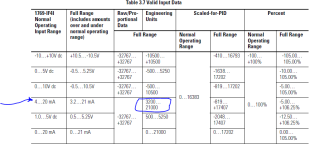
Trying to find out why , I researched (A LOT) to be sure that the RawMin and RawMax for the IF4 should be 4000 and 20000 and NOT 3200 and 21000.


Just to keep it simple, according to the book the 1769-IF4, 4-20ma range and 4-20ma Input Value the Engineering Units should be 4000 to 20000. So far so good. But when I get to the book for the 1769-IF4I, it throws in the "Full Range" and that's where I'm getting confused. It says RawMin and RawMax should be 3200 and 21000.

Here's the question:
Should RawMin and RawMax on the IF4I be 4000 and 20000? Considering the "Full Range" is 3.2-21ma, which is more than the usual 4-20ma.

Or did someone before me fail to update the RawMin and RawMax in the different 1769-IF4(I) cards?

I thought I had it figured out long ago until I found these settings/configs similar and in my research everyone is mentioning "Full Range", or maybe that was just in the 1756-L7X stuff where -32768 to 32767 comes in.

I would so appreciate any help because I can't find this specific of a question ANYWHERE.:confused:
 
I haven't ever given it as much thought as you, but Full Range is usually the current the module will still detect and convert analogue values, use the Over or Under range flags to read if it goes outside of the normal range.

Your engineering units still stay @ 4000 to 20000 for scaling purposes, because unless you have a problem, that is where they are always going to fall between.

You can put a ALMA in to fire an alarm if the sensor is out of range, or read the info straight from the module.
 
Let me ask it another way...
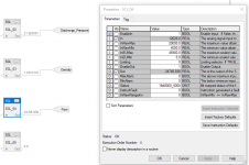
Is RawMin and RawMax on the SCL Block to be set to the 4000 and 20000 because that's what the transmitter is sending me? Or is it for 3200 and 21000 because that's what the AI points "Full Range" is?

SCL_Block.png
 
Here's the question:
Should RawMin and RawMax on the IF4I be 4000 and 20000? Considering the "Full Range" is 3.2-21ma, which is more than the usual 4-20ma.
I don't think it matters in the SCL, as long as the two Raw-to-EU pairs are correct for the conversion/calibration at hand.


Let me ask it another way...
Is RawMin and RawMax on the SCL Block to be set to the 4000 and 20000 because that's what the transmitter is sending me? Or is it for 3200 and 21000 because that's what the AI points "Full Range" is?
I think the answer is neither; all that matters are the Min and Max raw calibration points.


E.g. the example has

  • In minimum: 4ma signal = 0EU engineering = 4000counts raw
  • In maximum: 20ma signal = 45900EU engineering = 20000counts raw
For signals between 4ma and 20ma, putting those numbers (20000counts/0counts/45900EU/0EU) into the SCL will provide the same results, arithmetcally, as

  • In minimum: 3.2ma = -2295EU = 3200counts
  • In maximum: 21ma = 48768.75EU = 21000counts
which changes the minimum by one-twentieth of the range (-0.8ma out of 16ma and -2295EU out of 45900EU), and the maximum by one-sixteenth (+1ma out of 16ma and +2868.75EU), but the resulting calibration would be the same line on a plot.

The only difference might be if the SCL will either return 0 for any signal below 4ma (4000counts), or return 45900 for any signal above 20ma (20000counts). Perhaps that is what the [Limiting] parameter is for?


I assume the reason for the extra room in the full range, beyond the 4-20ma nominal range, on the ends is to make it possible to perform an in situ linear calibration test, where either or both of the test points are outside the normal range.


Look at it this way: if we had NIST-traceable test samples (weights?) of 10000EU and 40000EU to apply to the sensor for an in situ calibration, we wouldn't even be wondering about Nominal vs. Full Range; we would put in the counts read in from the 10000EU and 40000EU samples into RawMin and RawMax, respectively.


Or, if instead of doing an in situ calibration, we know it is close enough to use the datasheet specs for the sensor that say 4ma is 0EU and 20ma is 45900EU, then we use 20000counts/0counts/45900EU/0EU).
 
Thank you both for the responses because I have to get this right!!

And I'll admit drbitboy, most of your answer is over my head.

But the reason I'm making such a fuss over this is because it had a huge impact on our data being collected.

**Warning** Really fast explanation of the real world scenario that brought this on is coming:

We took Flow, Density and Pressure and remotely located them much further away and the difference of the settings was huge. The Density was actually the problem because
it and was scaled previously
RawMin 4000 and RawMax 20000
EUMin 1.0 and EUMax 1.6

And when I built the code for the new Instrument Location PLC and configured it for

RawMin 3200 and RawMax 21000
EUMin 1.0 and EUMax 1.6

It caused the Density to never come down to 1.0!! The lowest it got was 1.02 and with a flow of 28,000 gpm we were averaging 538 tons per hour on just water.

Am I making sense? Anyhow, I compared my new code to the existing older code and decided to give it a try and it corrected the problem.

But to your point, correcting it meant moving from the book numbers (3200 and 21000) to 4000 and 20000 for the RawMin and RawMax.

So should I just ignore the book and accept it for what its worth, the scale needs to be 4000 and 20000 because as you and Janner_10 said its a 4-20ma signal and should be scaled as such.

Sorry to be so anal about this, I just don't want to repeat this mistake no matter the platform (We're using Integer only AI cards in ControLogix as well!)
 
Summary


  1. The sensor/transducer element converts 1.0EU and 1.6EU to 4ma and 20ma, respectively, and linearly in between e.g. halfway would be 1.3EU and 12ma
  2. The -IF4I channel element converts 4ma and 20ma to raw 4000counts and 20000counts, respectively, and linearly in between e.g. halfway would be 12ma and 120000counts.
  3. Overall, those two elements compose a system that converts 1.0EU and 1.6EU to raw 4000counts and 20000counts, respectively, and linearly in between e.g. halfway would be 1.3EU and 12000counts.
  4. The SCL instruction is a digital model of that system in the inverse direction, converting raw 4000counts and 20000counts to 1.0EU and 1.3EU, respectively, and linearly in between e.g. halfway would be 12000counts and 1.3EU.
That fourth point is the key: computer programs, function blocks, and instructions are but models of some piece of the real world. The SCL instruction is no different, but to work (model the real world) correctly it needs to be configured correctly. The Nominal vs. Full ranges of the SCL instruction are irrelevant; what is relevant is that the SCL instruction accurately models the real-world system.


Detail

And I'll admit drbitboy, most of your answer is over my head.


Oh dear, perhaps a picture is worth a kWord?


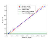
Figure_1.png


The red and blue lines represent the calibration (conversion from counts to EU) represented by the two SCL parameter sets (20k/4k/1.6EU/1.0EU vs. 21k/3.2k/1.6EU/1.0EU). If you find the raw count value [In] to the SCL instruction on the horizontal (bottom; raw counts) axis, and then go up vertically until you intersect the red or blue calibration line, then go horizontally from that intersection to the vertical (left, EU) axis, then the value at that vertical axis is the EU value corresponding to the input raw counts for that SCL instruction as scaled.


N.B. for any 4-20ma signal, the SCL parameters do not change the raw counts sent to the SCL instruction; e.g. when the signal is 12ma, the raw counts will always be 12000, and that will be the raw input to the SCL instruction. This is the real world you are trying to model with the SCL instruction. However, note also that the different SCL instrcution scaling parameters do affect the output EU value (i.e. the SCL model) for any given input raw count value.


And when I built the code for the new Instrument Location PLC and configured it for

RawMin 3200 and RawMax 21000
EUMin 1.0 and EUMax 1.6

It caused the Density to never come down to 1.0!! The lowest it got was 1.02 ...


The left-right position of the vertical black line represents a liquid with a density of 1.0: the sensor/transducer sends a 4ma signal to the -IF4I card's channel; that channel in turn sends a raw 4000count value to the PLC and the SCL instruction. That raw count input of 4000 intersects the red (20k/4k) line at an EU of 1.0 (lower green horizontal line), which is what the SCL instruction returns when configured for 20k/4k; the same raw count input of 4000 intersects the blue (21k/3.2k) line at an EU of 1.02 (upper green horizontal line), which is what the SCL instruction returns when configured for 21k/3.2k.

N.B. if the sensor/transducer will never send a signal less than 4ma, then the -IF4I channel will never send a raw count value less than 4k to the PLC, also never to the left of the black line in the plot. So the SCL instruction, when configured for 21k/3.2k/1.6EU/1.0EU, cannot return an EU value below the intersection of the vertical line at 4k raw counts and the blue line i.e. that SCL instruction cannot return an EU value below 1.02.
 
Excellent! I finally get it! I'm sorry to drag you through the remedial parts, but for what it's worth, that all made perfect sense! And is by far the best explanation I've seen of this yet. For my brain waves anyways.

And the addition of the picture was perfect!

I'll definitely be saving that response and re-reading it for a long time.

My teachers always said it takes me forever to get things sometimes, but when I do!........:ROFLMAO:

:geek:
 
whoops, there is a typo (one that I noticed, anyway) in my previous post in this thread: in point 4 of the Summary, the first 1.3EU should be 1.6EU.


I'm glad you understand; note that what I wrote here is only a visual expression of what I call the Secret of Engineering: multiplying by one; see post #10 of this thread https://www.plctalk.net/qanda/showthread.php?t=123939; hopefully you will never have to puzzle over this kind of problem again, because you will know it.
 

Similar Topics

Hey everyone, Doing a project for a VFD fan controlling the temperature of the condenser at an arena. The VFD replaces a two-motor setup that was...
Replies
7
Views
2,758
I'm in the process of installing a new 1769-L30ER controller as a retrofit to a 1794-L34. I'm trying to find out if I can load the firmware and...
Replies
1
Views
638
Good morning everyone. I have a situation that is really stumping me. I have three separate but identical machines, all running 1769-L30ER PLCs...
Replies
11
Views
3,521
Good afternoon. I have an issue that I have never encountered before and am uncertain of where to start. I have three machines, all with...
Replies
0
Views
944
Hey everyone, I am trying to message to a IndraControl L45 controller that I do not have access too. I have been given given a list of addresses...
Replies
3
Views
1,333
Back
Top Bottom