RS Flip Flop

suranjan

Member
Join Date
Jan 2003
Location
57074 Siegen
Posts
5
Hello,
I am a student.I have PLC progrmming this semester.Would anybody pls make me understand how RS Flip Flop functions?
 
Last edited:
To adjust the clocked RS latch for edge triggering, we must actually combine two identical clocked latch circuits, but have them operate on opposite halves of the clock signal. The resulting circuit is commonly called a flip-flop, because its output can first flip one way and then flop back the other way. The clocked RS latch is also sometimes called a flip-flop, although it is more properly referred to as a latch circuit.

The two-section flip-flop is also known as a master-slave flip-flop, because the input latch operates as the master section, while the output section is slaved to the master during half of each clock cycle.


The edge-triggered RS flip-flop actually consists of two identical RS latch circuits, as shown above. However, the inverter connected between the two CLK inputs ensures that the two sections will be enabled during opposite half-cycles of the clock signal. This is the key to the operation of this circuit.

If we start with the CLK input at logic 0 as initially depicted above, the S and R inputs are disconnected from the input (master) latch. Therefore, any changes in the input signals cannot affect the state of the final outputs.

When the CLK signal goes to logic 1, the S and R inputs are able to control the state of the input latch, just as with the single RS latch circuit you already examined. However, at the same time the inverted CLK signal applied to the output (slave) latch prevents the state of the input latch from having any effect here. Therefore, any changes in the R and S input signals are tracked by the input latch while CLK is at logic 1, but are not reflected at the Q and Q' outputs.

When CLK falls again to logic 0, the S and R inputs are again isolated from the input latch. At the same time, the inverted CLK signal now allows the current state of the input latch to reach the output latch. Therefore, the Q and Q' outputs can only change state when the CLK signal falls from a logic 1 to logic 0. This is known as the falling edge of the CLK signal; hence the designation edge-triggered flip-flop.


--------------------------------------------------------------------------------

By going to a master-slave structure and making the flip-flop edge-triggered, we have made sure that we can precisely control the moment when all flip-flops will change state. We have also allowed plenty of time for the master latch to respond to the input signals, and for those input signals to change and settle following the previous change of state.

There is still one problem left to solve: the possible race condition which may occur if both the S and R inputs are at logic 1 when CLK falls from logic 1 to logic 0. In the example above, we automatically assume that the race will always end with the master latch in the logic 1 state, but this will not be certain with real components. Therefore, we need to have a way to prevent race conditions from occurring at all. That way we won't have to figure out which gate in the circuit won the race on this particular occasion.

The solution is to add some additional feedback from the slave latch to the master latch. The resulting circuit is called a JK flip-flop.
 
Sameer,

Where are the diagrams that you refer to in the text. Is this your own work? If not, don't you think it would courteous to at least cite the reference from which you copied it. Otherwise, there's a nasty name for what you've done. That name is plagiarism.

Suranjan,

The information about various types of flip-flops is typically included in courses on Boolean algebra and digital circuits. It is interesting stuff to know and understand because it forces you to consider things that you might not otherwise think of, particularly in regards to the behavior of logic circuits under non-standard or less frequently occurring conditions. Its similar to the way that the study of geometry trains you to think logically.

Having said that, I'm not aware of any PLC that includes any type of flip-flop in its function set. I have seen some HMI devices and SCADA software that included a 'toggle' command in their functionality. The most frequently encountered industrial application of the flip-flop circuit is to use a single command to flip-flop the state of a device. By that I mean; if it's on, turn it off; if it's off, turn it on. If you're interested, that topic has been discussed to death on this forum. Search through the archives for a plethora of posts on the subject.
 
Having said that, I'm not aware of any PLC that includes any type of flip-flop in its function set.

Siemens S7 for the 300/400 does, I will have to locate the manual and the instruction but I know it has it, I have offered it as an example before concerning flip flops on here.
 
Hi

I am a newbie too but i can say rsdoran is right, since i downloaded the pdf manuals in spanish from siemens site. I saw the RS and SR instructions mentioned there. I also had downloaded the German manual, for language learning purposes. The RS Flip Flop rücksetzen instructions in KOP (ladder programing) starts in page 1-12. I hope it helps. Couriously i was reading that precisely today.
I could post the url to the download if you want me.

Saludos

Héctor
 
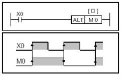
What's amazing to me is these plc's can do such complicated math instructions, but it looks like some don't have a simple function for a flip flop. I've read some of the past post for flip flop's and seen various differences in the way people code a simple flip-flop cicuit.
It seems like a lot of work to get a flip flop circuit.
Anyways, this may be of some help to any Mitsubishi FX users.

FX Programming Manual
Mitsubishi Electric Company
www.meau.com
1999

Hows that Steve? :D

diag1.jpg
 

Similar Topics

I am having this issue trying to figure out how to do this. I have a Hydraulic ram that travels when a machine is running. The ram extends to the...
Replies
31
Views
9,441
Hi everyone, I'm learning ladder logic and have built a flip flop circuit (see pic) from an online tutorial. Closing the switch A is meant to...
Replies
19
Views
6,876
I found and fixed issue. B3:3 was used in MOV.
Replies
11
Views
2,551
I am calculating power factor from samples of voltage and current. Calculation is done by multiplying voltage and current samples. What Im...
Replies
0
Views
1,629
Hi all, my first post here, I've been lurking for a while. I'm a beginner and I hit a wall on one of my first projects I'm working on. I know it...
Replies
6
Views
2,525
Back
Top Bottom