PLC5 To Controllogix Conversion

pravinshinde

Member
Join Date
Feb 2009
Location
pune,India
Posts
57
Hi,I am doing PLC5 To Clx conversion project.I have problem with I/O cofiguration in ControlLogix.

1) when I connect RIO cable to new 1756-DHRIO E the ACTIVE status of 1771-ASB goes OFF.
2)In I/O configuration tree I got Yellow triangle.

Any Help
 
Welcome to the Forum !

You must post more detail if you wish to solve this problem. All I can tell you now is that "your 1756-DHRIO configuration is wrong".

Physically, you must make sure the rotary switches on the 1756-DHRIO are set to select RIO Scanner for the channel to which you are connecting. You must also be sure that the same color insulated wires are connected to pins 1 and 2 on the RIO plug as were connected on the PLC-5 controller.

The 1756-DHRIO will also scroll status messages across the display for each channel.

In RSLogix 5000, you must correctly set the Data Rate (57.6, 115.2, or 230.4 kb/s) and exactly duplicate the Rack number, Starting Group, and Rack Size settings that were in the PLC-5.
 
Hi Ken Thanks for your quick reply.
I will explain you in detail.

1)For 1756 -DHRIO E module ,Channel A and B I have selected 1 i.e RIO Mode.
2)In RSlogix 5000 I have selected CH A and CH B as RIO and 57.6 K baud rate.
3)In slot 0-L62,slot 1-EN2T,slot 3-DHRIO E up to here I don't have any problem.But when I configure 1771-ASB as a logical rack it gives me yellow triangle and On 1771-ASB module I am not able to get ACTIVE status of adapter.When I connect RIO cable to PLC5 I get ACTIVE status.

If you need any more detail I will provide you.Actually it is water treatment plant running with PLC5.I have limited shutdowns and within that I have to switsh over to CLX
 
First, let's be certain about the wiring. The PLC-5 and the 1756-DHRIO plugs face opposite directions but have the same pinouts relative to the round side of the plug. You can take the 3-pin plug from a PLC-5 RIO scanner channel and plug it directly into the 1756-DHRIO module's RIO scanner channel without changing any of the wiring.
 
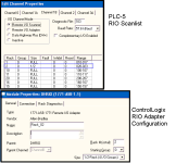
In RSLogix 5000, you insert an Adapter object in the I/O tree that matches each entry in the Scanlist of the PLC-5 RIO channel.

Three addressing values must match: the Rack Number, the Starting Group, and the Rack Size.

Remember that Rack Numbers are in Octal (base 8) numbering. Starting Groups can be 0, 2, 4, or 6. Rack Sizes can be Full, 3/4, 1/2, or 1/4.

The second tab of the Module Properties will give you a more precise error code than the "yellow triangle" icon.

RIO_Scanlist_Comparison.PNG
 
I realize you have already committed to the 1756-DHRIO module, but this is a good opportunity to mention the 1756-RIO module's features.

The 1756-RIO is a single-channel RIO Scanner module (there is no DH+ functionality) that takes the configuration and block transfer functions out of the ControlLogix and places them in the module, using a configuration add-in for RSLogix 5000.

The drawback of this module is that it requires some import/export and aliasing that can be complex.

The great benefit of this module is in situations like yours; it can be loaded with a "Listen Only" firmware that allows it to be connected to the RIO network and collect both Input, Output, and Block Transfer data passively. You can write your translated program (PLC-2, PLC-3, PLC-5, etc) in the ControlLogix and test it with the real machine I/O before transitioning to Scanner mode.

When you have very short shutdown windows because of high production and uptime demands, this module is a very good tool. It requires more engineering time up front and during the conversion, but greatly reduces troubleshooting and downtime during the switchover.
 
Additional information about that remote chassis would be helpful as well.


  • What size chassis (4, 8, 12, or 16-slot?)
  • What Addressing Mode (1-slot, 2-slot, 1/2-slot)?
  • What Rack # is it configured as (dip switches on the ASB)?
OG
 
Hi,
I have checked the wiring twice-thrice.
1-Blue,2-shield,3-Clear.
see when I configure only L62,EN2T,DH+/RIO there is no problem in Clx I/O tree,But as soon as I configure logical rack this gives me yellow triangle.Logical Rack congiguration is 100% correct becoz for testing I am configuring only one rack.
But in both cases 1771-ASB is not active.
 
I had the same comm error. It was my baud rate double check plc5 baud
mine needed to be 115k. Also you need to change the plc5 main rack to new rack address on 1771-asb So find open rack address to assign to the old main rack and Configure 5000 to that rack number.
 
I was assuming that the original poster was using an existing 1771-ASB in an existing chassis because he stated that it works when he connects it to the original PLC-5 scanner.

The most common mistake I've made is when I took a PLC-5 out of a chassis and substituted a 1771-ASB without changing the backplane switches. You definitely have to set the backplane switches (a single vertical DIP switch) differently for a PLC-2, a PLC-5, or a 1771-ASB in the chassis.

My guess is that the original poster's 1771-ASB is not set for the Rack Number he thinks it is.

Post the settings of the DIP switches on the 1771-ASB, as well as the Series and Firmware Revision of the 1771-ASB.

Also remember that short networks still need proper termination. At 57.6 or 115.2 kb/s you need one 150 ohm resistor at each end. At 230.4 kb/s you use 82 ohm resistors. Do not omit them just because the network is short or because "it worked before".
 
For testing I am configuring only one rack.
It is ahving single slot addresing and 16 input modules i.e.Full rack(8 I/O Groups)

Ok, we have to be careful here. You describe 16 input modules and 1-slot addressing. That is not one "rack". That is two "racks".

It sounds like you have a 16-slot chassis and for the purposes of communications, what is in the slots is not relevant.

Now, as Ken asks, please post the settings for the DIP switches on the ASB and on the chassis itself along with the series and rev of the ASB module. This is critical information.

OG
 
Good catch, OG ! And it's going to get more interesting because one of his scanner channels is in Complementary mode.

Please post the following information:

1. What Rack, Starting Group, and Size have you defined in your RSLogix 5000 I/O tree ? A screenshot or the *.ACD file are acceptable.

2. Which channel of the PLC-5/60 are you connecting ? The Rack/Slot/Group will tell us that implicitly but I want to be able to describe how they differ.

3. What exact modules, in what exact order, are in the chassis ?

4. What are the DIP switch settings of the 1771-ASB ?
 
Last edited:

Similar Topics

Hello, I am currently converting a project from PLC5 to ControlLogix. I have migrated the program from Logix5 to Logix5000 and any Block Transfer...
Replies
4
Views
3,345
Hi all, I have used your forum a lot in the past for helpful hints, but I could not find anything on this question. I have a project where I am...
Replies
2
Views
2,858
Hi All! I am going over some PLC 5 code in preparation of an upgrade to a ControlLogix processor. A rung of code in the 5 has a compute block with...
Replies
7
Views
2,617
When I attempt to convert my PLC5 (.PC5 program) to Controlllogix in RSLogix 5000 (v 20.01), it gets about 1/2 way then I get this error: Fatal...
Replies
4
Views
2,924
The DTR requires a DINT This is a PLC5 conversion to Controllogix without altering the HMI So the N files must be Ints not Dints Here I have moved...
Replies
5
Views
2,654
Back
Top Bottom