Hi PL_c
TO/FROM:
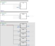
The "TO" function is for sending/writing data to a special module whereas the "FROM" function is for reading data from a special module. A special module would be any module excluding digital IO modules or any module that can be configured.
There is a difference between the TO and FROM functions depending on what PLC model you are using. for example the TO and FROM functions for the AH arnge of PLCs from Delta have three "m" registers. As the photo you posted only has two "m" registers I am going to assume you are using the DVP range.
-m1, m2 and n are the same for the TO and FROM functions.
-m1 is where you enter the number of the special module, connected to the right hand side of the CPU, that you want to communicate to. Special modules connected to the right hand side of the CPU start at 1 going left to right, and special modules connected to the left hand side of the CPU start at 100 going right to left. It does not matter if you have digital IO cards inbetween as they do not get counted i.e. your system could be as follows - cpu, digital input, digital input, analogue input, digital output, analogue output
The analogue input card would be special module 1 and the analogue output card would be special module 2.
-m2 is the control register you are wanting to write data to or read data from. the control registers are listed in the instruction document for each special module.
-S is the data you are wanting to write to the special module's control register. This could be configuration data or an output value.
-n is the number of successive words you are wanting to write. I have never needed to write more than one word at a time so I keep this as 1.
-D is the PLC register address of where you are wanting to store the information you have just read in.
Example:
I have a thermocouple card (DVP-04TC-S) connected to the right hand side of my DVP-12SE cpu.
I want to configure the card's four input channels for a type J thermocouple. (TO function)
m1=1 as it is the first special module.
m2=1 as according to the instruction sheet CR1 (control register 1) is the register where I can set what type of thermocouple is connected to each input channel.
S=0 as according to the instruction sheet b0-b2=0 sets channel 0 to type J, b3-b5=0 sets channel 1 to type J, b6-b8=0 sets channel 2 to type J and b9-b11 sets channel 3 to type J, b12-b15 are reserved. So setting CR1 to 0 would set all the input channels for a type J thermocouple.
n=1 as I am only sending 1 word of data.
I want to be able to read in the average temperature data in 'C for each channel from the thermocouple card. (FROM function)
m1=1 as it is the first special module
m2=6 as according to the instruction sheet CR6 is where the average temperature in 'C for the first channel is stored.
D=D100 as this is where I want to store the average temperature for that particular channel.
n=1 as I am only reading 1 word.
SCLP:
The SCLP, as you have probably guessed, is for scaling one value to another value within a certain range. You could use SCAL but I prefer DSCLP(double word version of SCLP).
S1 is your input value. i.e. the value you are wanting to scale to another range.
S2 is the first register of where you stored the ranges that the SCLP function will work with, and this continues for 4 registers for the SCLP and 8 registers for the DSCLP.
D is your output value i.e. the scaled result of the calculation.
Example:
I have a system where an operator is able to set how much a valve is open by entering a value of 0-100 on an HMI. The 0-100 that the operator enters on the HMI gets stored in D50. Lets assume that the analogue output card works on a range of 0-4000 points to give an output of 4-20mA. Lets assume you are going to use D500 onwards for the parameter registers.
Summary- your input range is 0-100, your output/scaled range is 0-4000
First set up your parameters:
D500 = maximum source value, I prefer to call it maximum input value.
D501 = minimum source value, I prefer to call it minimum input value.
D502 = maximum destination value, I prefer to call it maximum scaled value.
D503 = minimum destination value, I prefer to call it minumum scaled value.
store 100 in D500, 0 in D501, 4000 in D502 and 0 in D503.
S1 = D50 (the 0-100 from the operator).
S2 = D500 (the first parameter register).
I hope this helps you.
Caveat: I wrote this in a hurry so there might be a mistake or two

Cheers
Guy


