Powerflex 525 to PLC (non-Ethernet connection)

Tfackler2000

Member
Join Date
Jan 2022
Location
Ohio
Posts
1
I am looking for some help with a project that I am working on to finish my maintenance apprenticeship. Any help would be greatly appreciated. My instructor and I will be very thankful.

I am trying to connect a PLC to a Powerflex 525 VFD. This is just a small conveyor based project in the classroom. The current instructor is new and is struggling with the same issues I am having. I want to use the outputs from the PLC to control the start and stop of the drive. I am not sure if this would be considered a 2 wire setup or a 3 wire setup. The way i have this connected right now is output 1 to terminal 1 (Stop) and output 2 to terminal 2 (start/run/fwd) and output 3 to terminal 3 (start/run/rev). The VFD is set as SRC. I can change the parameters using CCW and am very familiar with doing this. As of this moment when I turn power on to the system some of my outputs are flashing on/off. I am not sure if this is from the VFD, like some kind of feedback, or if there is another issue somewhere else. I will try to answer any questions concerning my project to the best of my knowledge.
The PLC is a 1769-L23E-QB1B
The VFD is a PowerFlex 525
Again any and all help is greatly appreciated.

Thank you
 
Welcome to the PLCTalk forum community !

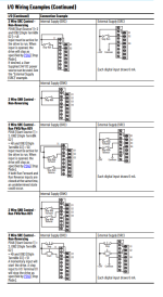
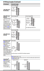
I am not particularly happy with the wiring diagrams in the PowerFlex 520 series User Manual, especially the overall wiring diagram on Page 41. It looks to me like somebody pasted two rows of dry contacts next to one another and said "good enough !". It makes sense once you know what the gap in the line leading to the DC Common terminal 4 means, but isn't a great at describing it to a novice. The separate Digital Input circuit diagrams starting on Page 45 are better and clearer.

The overall I/O circuit summary diagram shows you that the opto-isolators in the Digital Input section are light-emitting diodes that are wired both ways, so they can be turned on by a 24V difference of either polarity.

It shows that when the configuration jumper is set for "SRC", the opto-isolator circuit on the input is internally connected to DC Common (Terminal 4). That means that the circuit connected to the digital input needs to provide a "Source" of +24V to be logic = true. That is standard in North America and Europe.

The easy way to do discrete control of these drives is to wire a dry contact or pushbutton or relay between the Digital Input terminal and the internal +24V power supply terminal on the PowerFlex itself (terminal 11).

When the configuration jumper is set for "SNK", then the opto-isolator circuit is internally connected to +24V, so the digital input needs to be connected through a contact to DC Common, which is called a "Sinking" input circuit. This is standard in Japan.

But your system is wired up to a CompactLogix PLC. The 24V supply on that PLC isn't necessarily at the same voltage as the internally-sourced 24V on the PowerFlex drive.

Take a look at the 1769-L23E-BB1B installation instructions, which show the DC Outputs on Page 19.

All the DC Outputs on that CompactLogix are electrically grouped together: you can't isolate them individually or in groups of 2, 4, or 8 (which is common on some other devices).

If the PowerFlex is the only thing this PLC is connected to, then just connect the CompactLogix output section "+VDC" terminal to the PowerFlex +24V terminal 11, and the "DC COM" terminal to the PowerFlex Digital Common terminal 4.
 
About "2 wire" and "3 wire" VFD control: this is legacy stuff made so that a VFD can be configured to work just like a motor starter on/off circuit.

"2 wire" control is like a selector switch: you close one contact and it runs the drive. Open the contact, and the drive stops.

"3 wire" control is like a latching on/off pushbutton and motor contactor circuit: you keep the STOP input = True and momentarily close the START circuit. When you want to stop the drive, you open the STOP circuit.

It sounds like your application wants to use one output = Run FWD, and one output = Run REV. When both outputs are OFF, the drive should stop.

Note that Digital Input 1 can't be programmed for anything but STOP. So put a jumper on it to tie it to +24v (terminal 11).

Set t062 Digital Input 2 = Run FWD (value 48)
Set t063 Digital Input 3 = Run REV (value 50)
Set t064 (2-Wire Mode) = 0 = "Edge Trigger" (default).

I have not used discrete wired PowerFlex 525 drives as extensively as I have used them controlled over a network, so I could certainly be mistaken even on these simple elements. But that's what I read in the manual and is my experience after (counts on thumbs) a very long career working with/for A-B.

page 45 of the manual shows the standard ways for wire control, it should make it fairly easy for him to set it up and go, both internal voltage and external voltage are shown as examples in sinking and sourcing applications.


Edit: It is funny to show up to a customer and see that they have a newer powerflex 753 or 525 installed on something, and they're only using the simplest of control. Outputs to the directions, either a set reference speed, or an analog input signal and that's it. Then, off to another customer using multiple powerflex 4's all controlled through message instructions through HMI and program control swapping drive parameters for multiple motor use.... the world is upside down right now.

wiring.PNG wiring2.PNG
 
Last edited:
page 45 of the manual shows the standard ways for wire control, it should make it fairly easy for him to set it up and go, both internal voltage and external voltage are shown as examples in sinking and sourcing applications.


Edit: It is funny to show up to a customer and see that they have a newer powerflex 753 or 525 installed on something, and they're only using the simplest of control. Outputs to the directions, either a set reference speed, or an analog input signal and that's it. Then, off to another customer using multiple powerflex 4's all controlled through message instructions through HMI and program control swapping drive parameters for multiple motor use.... the world is upside down right now.

I know its a bad philosophy, I too like using Eth/IP to control drives and making use of their advanced communication methods. However, If I install an Ethernet controlled VFD, a tech on shift cant replace it if it fails. They need to match firmware, datalinks ect. If its hardwired and the parameters are written on the drawings, then I can avoid ill timed call ins and all the frustration. Sometimes keeping it simple is simply to keep sanity, perhaps at the cost of the projects integrity....
 
Thank you for pointing out, Ian, that the Digital Input circuits on the PowerFlex 525 operate just as well using the onboard +24V and DC Common (terminals 11 and 4) as they do with external +24V and DC Common connections.

They're really not much more complicated than a simple optoisolator, which is why they're represented schematically as just a pair of LEDs wired up in opposite polarities so they'll work wired for SNK or SRC.

This is actually a great lesson for a classroom. You need to make an initial design choice about whether to use the internal PowerFlex power supply for digital I/O, or use an external one. This can lead to discussions about the typical power capacity of small onboard supplies, and about isolation between bulk power supplies and I/O supplies, and about E-Stop switched circuits.

My guess (and it's only a guess) is that Tfackler2000 has connected the +24V from the external power supply that is serving his PLC Output module via those output terminals to the Digital Inputs, but has not connected the DC Commons together, so the voltage seen by the Digital Input circuit is "floating".
 
Right Ken

not to mention the importance of snk/src when it comes to controls.

the phrase, "If the light on the sensor is on, it's working, it doesn't make any sense why the PLC input isn't turning on!!!!" comes to mind. šŸ™ƒ
 
I know its a bad philosophy, I too like using Eth/IP to control drives and making use of their advanced communication methods. However, If I install an Ethernet controlled VFD, a tech on shift cant replace it if it fails. They need to match firmware, datalinks ect. If its hardwired and the parameters are written on the drawings, then I can avoid ill timed call ins and all the frustration. Sometimes keeping it simple is simply to keep sanity, perhaps at the cost of the projects integrity....

I can't count the times between Device Net and Ethernet controlled drives when my customers that have all the drive config files can't get a replacement drive running. When they are hard wired there is no problem. I know I am a little slow at programing but by the time it takes me to get everything to communicate I can run a few wires back to the PLC + I can tell the customers guys to see if you have 24v on term#2. I don't need the work.
Keep it simple.
 

Similar Topics

Good Afternoon , I'm working on a project with a CompactLogix and PowerFlex 525's . I plan on having a HMI screen that will allow some...
Replies
8
Views
4,070
Hello everybody. I am a new poster to this forum, but have been using PLC.net to help me through issues for a long time now. So I have to say...
Replies
10
Views
3,462
Hi to all. We need to change a bad powerFlex 525 to a new one. How do you save the configuration to install in the new one? Thank you all for...
Replies
5
Views
233
Im trying to teach a couple of labs on VFDs at a community college. We have some motor control trainers with P525s and 3 phase motors from...
Replies
2
Views
244
New to vfds. I put in parameters. IP, but I get ethernet flashing and link solid. What did I do wrong?
Replies
9
Views
473
Back
Top Bottom