1756 if16 Analog Input

I still didn't try to install jumper.

well, that COULD be the source of ALL of your trouble ...

without the jumper, you might indeed have a certain amount of current (for example: 20 mA) following through your wires (and through your test meter) – BUT – if the jumper is not installed correctly then the amount of current that is actually flowing through the module's internal INPUT RECEIVER might not be 20 mA ... specifically, the current could be dividing – and flowing through other components inside the module ... (this is sometimes called a "backdoor" circuit) ...

there's no guarantee about all of this – but you really should install the jumper BEFORE you do anything else ... there's a reason for the jumper to be there – and if you don't connect it, then the module can't properly do its job ...

I need to wait weekend when factory stop Furnace.

sounds like a good plan – and I don't want to talk you out of it ... on the other hand, I know quite a few guys who would be willing to connect a small jumper wire on a 4 to 20 mA circuit – as long at the PLC program wasn't actively using that particular circuit at the time ... personally I think you should wait until the plant is shut down ...

And what do you mean to look in the scaling?

as near as I can tell by what you've posted, the scaling settings seem to be right ... what I meant was that you should make sure that everything ELSE is correct – before you mess around with the "calibration" ...

here's the game plan that I recommend (from where I sit on the other side of the world – and based on what you've posted so far) ...

install the jumper – then check your signals again ... I've got a hunch that you'll be pleasantly surprised by the results ...

good luck with your project ...
 
Last edited:
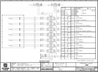
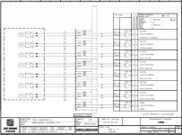
First group on Analog input(1iRTN; 3iRTN; 5iRTN; 7iRTN; 11iRTN; 13iRTN; 15iRTN; lead to O VDC ( 125.02 wire) and Jumper to RTN.


Wire from 25iRTN(also 19iRTN, 21iRTN, 23iRTN, 29iRTN, 31iRTN, 33iRTN,35iRTN) lead to 0 VDC(111.02 wire) but not to the RTN.

Is that a problem? o_O

Sema1.jpg Sema2.jpg
 
Here is wiring, so actually I made a mistake, jumper already exist. :sick:
Problem still remains.

I suspected that your jumper was present, else you wouldn't have even been in the ballpark with the data returned from the module. It appears to me that your primary issue is in failing to correctly account for your elevated zero when assigning the scaling parameters to your input. You have not yet told us what you have entered in the channel configuration, but I noticed that the values returned by the module at both 4mA and 20mA are exactly 77 counts less than what you desire.

You could correct this error by simply adding 77 counts to both scaling parameters in the module's channel configuration for scaling to Engineering Units. Perhaps your scaling parameters are correct and this error is due to the fact that someone has already tinkered with the calibration on this module and gotten it out-of-whack?
 
Wire from 25iRTN(also 19iRTN, 21iRTN, 23iRTN, 29iRTN, 31iRTN, 33iRTN,35iRTN) lead to 0 VDC(111.02 wire) but not to the RTN.

Is that a problem?

well, let's say that it's certainly SUSPICIOUS ... personally I'd bet a lot more than pocket-change that this is what's causing your problem ...

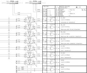
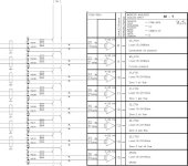
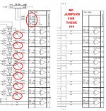
here's a sketch where I've put parts of your two schematics side-by-side to compare ... the top 8 channels have the jumpers shown ...

BUT ...

there are NO jumpers shown for the bottom 8 channels ...

note that ALL of your channels are marked as 4 to 20 mA inputs – so they ALL should have the jumpers ...

CAUTION! are you SURE that the transmitters that you're having trouble with are actually CURRENT types – not voltage? ... the schematics indicate that they're CURRENT – but personally I don't always trust schematics ... sometimes the original copies don't get updated when changes are made in the field ...

.

jumper_schematic.jpg
 
Last edited:
Ok, let's go from begining. 📚
I found that Shematics not good.
On place JUMPER exist on all channel.

But voltage between RTN(7,8,27 or 28) and 0 VDC is 0.356 V

Potential difference should be 0

I think that make a problem
 
I found that Shematics not good.


that type of thing happens ... a wise man once said: "If the terrain and the map don't agree – then trust the terrain."

On place JUMPER exist on all channel.


so you're saying that ALL of the channels DO have the jumpers installed – even though the schematic doesn't show them ... is that correct? ...

But voltage between RTN(7,8,27 or 28) and 0 VDC is 0.356 V


are you sure that you didn't mean to say "9, 10, 27, 28" for your RTN terminals? ... make sure that you're getting the terminal numbers correct ...

Potential difference should be 0
I think that make a problem


well, technically if all of the jumper connections are clean, bright, and secure – then all of the terminals that are jumpered together SHOULD be at the same voltage potential ...

but (once again) please make sure that you're taking your readings from the correct terminals ... since you mentioned the wrong numbers for two of the RTN connections, there's a possibility that you're probing the wrong terminals ...

please keep us posted on how this turns out – it's an interesting and instructional problem ...

.
 
Last edited:
Yes, all channels have instaled JUMPERS.


I mean voltage from 1756 between 9 RTN and GROUND is 0.356V, also 10 RTN and GROUND is 0.356 VDC; 27RTN and GROUND is 0.356 VDC ; 28RTN and GROUND is 0.356 VDC

Terminal 9=10=27=28=RTN 📚

Everything is clean,secure, bright but potential difference exist.

Thank you for support.

I will continue reporting
 
I mean voltage from 1756 between 9 RTN and GROUND is 0.356V, also 10 RTN and GROUND is 0.356 VDC;
Whoops! There is a poorly grounded point at one end or the other. If ground is 0 volts, then one end is not 0. If you have a grouding wire running along with some AC voltage conductors for a long distance, it can pick up induced power-line "noise" that shows up as a voltage.
 
I want to thanks everyone for help.🍻

Problem was at poorly grounded point which make a difference potential 0.356 VDC.
I brought another 0(-) VDC from UPS(24VDC) and problem is solved.
Now there is no potential difference :D
 
Problem was at poorly grounded point which make a difference potential 0.356 VDC.
I think that there is a group of technicians out there that think that a 24 volt control circuit needs a + (plus) signal, but that the - (minus) is no big deal because after all it is really "0 volts", then you can just connect that side of the circuit to the nearest earth ground point, and everything will work just great.

The problem is that the earth really is not a very good current conductor, and if that is the only return path that you have for the (-) side, it will result in your -24 VDC signal terminal running at something other than 0 volts to ground. Most of you are too young to remember those early telephone systems that had only 1 wire (1 conductor) running on the pole insulators. The other side of the signal (the "return") was carried only by the earth, with the negative signal wire running to a grounding rod at each telephone. Must I tell you that those phone conversations were full of static, noise, and missed words?

My grandfather was a fire watcher at a forest service fire tower, which was about a half-mile walk through the woods behind our farm. I used to climb up to the little cabin on top of the tower, and listen to Grandpa try to call the fire station with the old battery crank phone. After several efforts and much cussing, he would say "son, climb down and pi$$ on the ground rod, so I can hear what the he11 they are saying."

One thing that leads to this problem is thinking of the -24 volt side of the circuit as "0 volts". If it were truly 0 volts, you could disconnect it and everything would be the same, because a 0 potential can do no work or produce any current, so you might as well leave it disconnected, right? That side of the circuit must conduct some current, even if it has to travel through the earth to get back to its -24 source.
 
Last edited:

Similar Topics

Hello, we chose Allen-Bradley analog card 1756-IF16 for three 4-20mA current inputs for XFMR high side winding temp, low side winding temp and...
Replies
5
Views
2,759
Good Evening , I’m getting ready to integrate a Mettler Toledo IND 570 into a ControlLogix PLC , Analog 4-20 ma input card 1756-IF16 . I’m...
Replies
6
Views
2,304
Good Evening , I have a 1756-IF16 Analog Input card already installed in a working ControlLogix Rack. I need to add another Analog 4-20 ma...
Replies
1
Views
2,180
Hello PLCTalk Friends, I am interested in connecting one 2-wire loop powered 4-20mA transmitter to two analog input cards. In my program, I will...
Replies
2
Views
1,388
Is there a way to see what the actual field signal value is going into each channel of the Analog Input I/O card 1756-IF16? In other words, I...
Replies
4
Views
3,660
Back
Top Bottom