You are using an out of date browser. It may not display this or other websites correctly.
You should upgrade or use an alternative browser.
You should upgrade or use an alternative browser.
Bit Shift or Sequence?
- Thread starter Iandayen
- Start date
Yes, F1 operation happens if under 85 degrees and F2, F3, F4 are all inactive.
That's why I was thinking bit shift. 4 bits, 1000 =F1, 0100 =F2, 0010 =F3, 0001 =F4
And that works out great for shifting left.
Shifting right is where I am getting confused. If F1 is active and Temperature spikes to 100 degrees for 15 minutes, I need to shift that bit right 3 times.
Can I just write to that array instead of shifting the bit right?
Leave the BSL in place for under 85 degrees then depending on temperature could write to that array? Then use those bits to activate F1-F4 operations?
You need to buffer the BSX instruction activations so they see a transition.
Bit shifting is not a good choice for this problem. I tried to do it with BSL/BSR instructions. I haven't tested it thoroughly but I think it works. I shift a 1 in the array at the LSB when F1 needs to turn on and shift that bit to the right when the other conditions are met. This way you can use a XIC .0 to turn F1, XIC .1 to turn F2, XIC .1 OR .2 to turn on F3, etc.
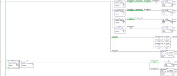
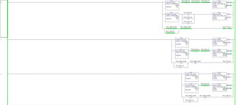
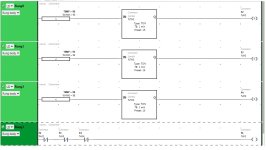
I would go with a longer but more explicit sequence. I've included part of an example. It's easier to troubleshoot, easier to make additions and exceptions to and easier to read.
Last edited:
drbitboy
Lifetime Supporting Member
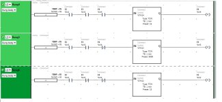
Eight rungs ([one timer + one transition] per range) to allow logic to skip, or at least shorten, the time to transition more than one combination; this is how I interpreted Lare's post #3.
In normal operation I would expect the temperature to move slowly through each range over time and this approach should behave reasonably. However, if the temperature ever jumps* over one or more ranges, two timers for different ranges will start and complete on the same scans, and the intermediate ranges either will be skipped or be current for only one scan, so caveat emptor.
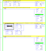
The image below shows the logic for first two fan combinations, F1 and F1.5, during the timing* before a transition from the former to the latter; the logic for F2, F3, and F4 is similar.
PDF report with the full program is also attached.
* broken sensor; manual override
** T4:1/EN is 1 and T4:1.Accum is non-zero

On ladder I would code it this way. Much easier to understand than shifting bits  .
.
There is also maybe need to add couple extra rungs.
Controlling F1 to shut F1 down completely on certain temp?
Also maybe extra set latches for F1, F2 and F3 so that if F4 is controlled, also F1,F2 and F3 are setted on.
(This is not maybe needed as temp rising should start all fans same time even)
p.s TM13 should be also 15mins, typing error there.


destination unknown
Member
drbitboy
Lifetime Supporting Member
Sidebar: I think some of these solutions have not picked up that the OP process description has each Fn state (combination) representing the state of all four fans, i.e. "F1" is not Fan 1 on/off state alone, "F2" is not Fan 2 on/off state alone.
OkiePC
Lifetime Supporting Member
Sidebar: I think some of these solutions have not picked up that the OP process description has each Fn state (combination) representing the state of all four fans, i.e. "F1" is not Fan 1 on/off state alone, "F2" is not Fan 2 on/off state alone.
Yep, and in "real life" there will be things like minimum run and stop times (maybe) which can serve as anti-short cycle timers and probably fail-overs to switch up the selected pattern in the event that a fan fails to start.
drbitboy
Lifetime Supporting Member
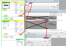
One more approach with three rungs, but only 8 instructions per Fn combination; F3, F4, and the output steps are shown in the image below.
What I like about this one is that the TON rung logic is more or less visually identical to the process description, as is the TOF rung logic. Also, there are only four instructions between those algorithms that turns each combination on or off.
TL;DR
Also note that the statement
Final note: For those who notice the incnsistency in the numbering of the timers in the PDF, timer control T5 apparently does not work on my MicroLogix 1100, so it uses T8 instead.
What I like about this one is that the TON rung logic is more or less visually identical to the process description, as is the TOF rung logic. Also, there are only four instructions between those algorithms that turns each combination on or off.

TL;DR
Also note that the statement
- temperature has been above 95deg for at least 15 minutes
- temperature has been above 90deg for at least 15 minutes
Final note: For those who notice the incnsistency in the numbering of the timers in the PDF, timer control T5 apparently does not work on my MicroLogix 1100, so it uses T8 instead.
These have all been amazingly helpful.
I also thought about the if temp >90 for 15 minutes is also true for if temp >95 for 15 minutes as well.
I was thinking about using the enable bit on the higher temp ranges as an interlock for the lower temp ranges and as a reset for those timers.
That way if the timer for the 95 or over is active it prevents the lower temp timers from even being enabled.
This is in a large building and the temperature sensor is an ambient temperature sensor. The temp swings probably won't go from 85 to over 95 or 98 in under a 15 minute span, but the code needs to be there just in case for some odd reason it does.
I've uploaded a PDF that shows the fan operations to help a bit with the confusion.
I haven't had much time the last couple of days but looking through all your suggestions I'm sure I can find something that works, I'm hoping to be able to work on it in the next day or so and will check back here and post what I have used from your suggestions.
drbitboy
Lifetime Supporting Member
[SF-1 High] and [SF-2 Low] are always Stop, [SF-1 Low] is always Start, and some of the bits are always the same in all bands, so there are effectively only five bits that need to be controlled:
The ordering of the bands is messy because it was based on a previous iteration, where all fans were off at the nominal range (Band 2). That said, I feel the per-band logic is clear, and it would be easy to change the compares to make the inter-band sequencing more orderly.
It takes 15 minutes to change the outputs any number of bands down, which may not be consistent with the first of the statements at the end of the process specification:
- SF-4, SF-5 and EF-1 are always the same as each other
- The other five have various arrangements and cannot be combined
The ordering of the bands is messy because it was based on a previous iteration, where all fans were off at the nominal range (Band 2). That said, I feel the per-band logic is clear, and it would be easy to change the compares to make the inter-band sequencing more orderly.
It takes 15 minutes to change the outputs any number of bands down, which may not be consistent with the first of the statements at the end of the process specification:
- Goes down 1 level for every 15 minutes of temperature below 85
- Goes up 1 level for a temp rise of 5 degrees for more than 15 minutes
Last edited:
drbitboy
Lifetime Supporting Member
Shifting right is where I am getting confused. If F1 is active and Temperature spikes to 100 degrees for 15 minutes, I need to shift that bit right 3 times.
Btw, I think you will end up somewhere else, but there is an ugly answer to this query that will complete in one scan:
Code:
F4_15min  Bits/0
---] [--+--]/[------[BSR         ]---+----
        |           [Array  #Bits]   |
        |           [Control  ctl]   |
        |           [...         ]   |
        |                            |
        | Bits/0  ctl.EN   ctl.EN    |
        +--]/[------] [------(U)-----+
        |                            |
        +-----------[BSR         ]---+
        |           [Array  #Bits]   |
        |           [Control  ctl]   |
        |           [...         ]   |
        |                            |
        | Bits/0  ctl.EN   ctl.EN    |
        +--]/[------] [------(U)-----+
        |                            |
        +-----------[BSR         ]---+
                    [Array  #Bits]
                    [Control  ctl]
[... ]The correct answer is to assign 1 to the Bits INT, of course
drbitboy
Lifetime Supporting Member
I have a request for clarification from the OP.
Here is a restatement of the process behavior rules:
Here is a restatement of the process behavior rules:
- Band 1 if temperature below 85 for 15 minutes
- Band 2 if temperature between 85 and 95
- Band 3 if temperature over 95 for more than 15 minutes
- Band 4 if temperature over 98 for more than 15 minutes
- Goes down 1 level for every 15 minutes of temperature below 85
- Goes up 1 level for a temp rise of 5 degrees for more than 15 minutes
- For the 5 and 6, can we assume "level" means "band?"
- Does rule 6, +5deg for 15min => up 1 band, makes sense if rules 1-4 are in place?
- Say the process is in Band 2 with the temperature at 85deg. The temperature goes up 5 degrees to 90 and stays there for 15 minutes, so rule 6 says to bump the process up one band to Band 3. On the next scan, rule 3 is not satisfied, but rule 2 is, so the process drops back to Band 2 after one scan at Band 3, i.e. maybe 50ms. Is this desired behavior?
- If not, and the process should stay in Band 3, then say the temperature goes up another 5deg to 95 and stays there for 15 minutes. Rule 6 again says to bump the process up one band to Band 4. The process is now in Band 4 at 95 degrees. How can it leave Band 4?
- Say the process is in Band 2 with the temperature at 85deg. The temperature goes up 5 degrees to 90 and stays there for 15 minutes, so rule 6 says to bump the process up one band to Band 3. On the next scan, rule 3 is not satisfied, but rule 2 is, so the process drops back to Band 2 after one scan at Band 3, i.e. maybe 50ms. Is this desired behavior?
- The way rules 3 and 4 are stated, and assuming the temperature does not suddenly drop below 85 from band 3 or 4 to invoke rule 5, there should be no delay for a transition from either Band 4 or Band 3 to Band 2. Because on the scan when the temperature drops from 99 or more to 98 or less, the rule 4 condition is false, and the process cannot stay in Band 4. The same logic applies to Band 3. Is that correct?
- How does rule 5 execute?
- Say the process is in Band 4 with the temperature at 100deg. The outside temperature could never drop 16deg in one scan to be less than 85, but say it does, as OP suggests. The process should drop to Band 3 immediately (rule 4 condition is false), but not drop from Band 3 to Band 2 for 15 minutes (rule 5, assuming temperature stays below 85), and then to Band 1 another 15 minutes after that (again rule 5). Is that correct?
- Say the process is in Band 3 and the temperature drops to 84deg in one scan. The process should drop to Band 2 immediately (rule 3 condition is false), but not drop to Band 1 for 15minutes, which would happen anyway with the delay on rule 1. Is that correct?
drbitboy
Lifetime Supporting Member
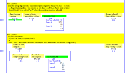
Assuming the above is correct, I modified the code to follow Rule 5 (drop one band per 15 minutes when temperature is less than 85 deg), and attach it here. It actually uses fewer instructions but is more complex.
I still don't know what to do about Rule 6.
TL;DR
I still don't know what to do about Rule 6.
TL;DR
- All four temperature transitions toward, but not beyond, the Band 2 range are immediate.
- Band 4 to 3
- Band 4 to 2
- Band 3 to 2
- Band 1 to 2
- The remaining five upward temperature transitions use the Band 3 and/or 4 TON timers and complete in 15 minutes
- Band 1 to 3: Band 3 on timer
- Band 1 to 4: Band 3 and 4 on timers run in parallel
- Band 2 to 3: Band 3 on timer
- Band 2 to 4: Band 3 and 4 on timers run in parallel
- Band 3 to 4: Band 4 on timer
- Rule 5 only applies to the remaining three downward temperature transitions, which all complete in 15 or 30 minutes
- Band 2 to 1: 15 minutes Band 1 on timer
- Band 3 to 1: immediate 3 to 2; 15 minutes 2 to 1
- Band 4 to 1: immediate 4 to 3; 15 minutes 3 to 2; 15 minutes 2 to 1
- As a result, a separate TOF off-delay timer is only needed for Band 3 in that one case when the temperature changes from the Band 4 range (T>98) to the Band 1 range (T<85).
- The process leaving Band 4 is always immediate when temperature drops out of Band 4 range (T>98)
- Immediate to Band 2 or 3 if new T>84
- Immediate to Band 3 if new T<85
- There is no need for a Band 4 off timer
- The process leaving Band 1 is always immediate when temperature rises out of Band 1 range (T<85)
- Immediate transition to Band 2
- One or both of Band 3/4 TON on timers may start
- There is no need for a Band 1 off timer
- The process transition into Band 1 only ever comes from Band 2, whether previous temperature
- was in Band 2 range (84<T<96) and Rule 5 is not in effect, or
- was in Bands 3/4 range (T>95) and Rule 5 is in effect.
- The Band 1 TON on-delay timer has logic to only run when T<85 AND process is in neither Band 3 nor Band 4 (i.e. AND process is in either Band 2 or Band 1,) so that Band 1 on-delay timer is in effect a proxy for a Band 2 "off delay" timer when Rule 5 is in effect.
- There is no need for a Band 2 off timer
- The process leaving Band 4 is always immediate when temperature drops out of Band 4 range (T>98)
- The only inconsistencies above are in the 3 to 2 process transitions, two of which are immediate and the other, where the temperature drops from the Band 4 range (T>98) to the Band 1 range (T<85), is not.
- That choice, whether to use Band 3 off timer, is made when the temperature drops out of Band 3 range (T>95).
- Because Band 3 is processed in the scan before Band 4, and with the assumption of either synchronous I/O and ladder scan or mapped I/O, when Rung 0004 below is scanned the [Process in Band 4] bit will be 1 if it was 1 from the previous scan
- [XIO Band3OnTimer/DN XIC ProcessInBand4] pair at the beginning of the rung is in effect a one-shot because if Band3OnTimer/DN is 0 then not (T>95), so not (T>98) must also be true, so ProcessInBand4 will be assigned 0 on a later rung in the same scan.
- So if
- the process will not be in Band 3 (Band3OnTimer/DN is 0 because not T>95),
- and the process was in Band 4 (Band 4 bit is 1),
- and the temperature is not in the Band 1 range (GEQ N7:1 85),
- then the transition out of Band 3 will be immediate the Band 3 off timer will not be used
- so the Band 3 bit is unlatched to break the seal-in on Rung 0005 that maintains the effect of the Band 3 off timer, which timer starts when Band3OnTimer falls from 1 to 0.
- Rung 0005 maintains that [Process in Band 3] bit until the off timer is complete, unless one of the following occurs.
- If the [Process in Band 3] bit was unlatched in the previous rung, the seal-in branch is false
- If temperature leaves the Band 1 range (not (T<85), the seal-in branch is false
- The temperature check on the seal-in branch by itself, without Rung 0004, is not enough:
- In the case where the temperature jumps from the Band 3 range to the Band 1 range, the process change from Band 3 should be immediate.

Last edited:
Similar Topics
Hi All. I have a very specific question about tracking using an encoder and bitshift register. We would like to use a Compact or Control Logix PLC...
- Replies
- 40
- Views
- 1,822
Hello. I've been using the answers in this forum for a while now, so thank you. Usually I can find the answer I'm looking for with a basic...
- Replies
- 8
- Views
- 809
Hi, I need some help write a PLC instruction. I am using Proficy Machine Edition 6.5.
Our indexing rotating table has 3 nests that are equally...
- Replies
- 15
- Views
- 4,062
Good morning (EST),
I am trying to implement the code below in on an S7-1200. It's barely half a dozen instructions, but I am stuck; I have not...
- Replies
- 26
- Views
- 5,788
I am having trouble figuring out how to track a product using a BSL instruction. The way that I have it set up is: I have an infeed eye that...
- Replies
- 10
- Views
- 2,762


