![]() ![]() ![]() ![]() ![]() ![]() |
||
![]() |
||
![]() ![]() ![]() ![]() This board is for PLC Related Q&A ONLY. Please DON'T use it for advertising, etc. |
||
![]()
|
New Here? Please read this important info!!!
![]() |
#1 |
Member
![]() ![]() Join Date: Apr 2018
Location: Toronto
Posts: 14
|
fine tune PID loop
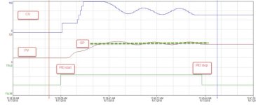
I am troubleshooting a PID loop developed and tuned by others. It is a heat exchange process, utilizing steam and control valve to heat up process water from 0 to 80 degree in 1.5 minutes. PID equation is independent and current Kp value is 25, Ki value is 10 andn Kd is 0. See attachment for trend of PV and CV. CV open from 0 to 100% and PV obviously go into oscillation status.
What procedure shall I follow to identify right Kp and Ki value and allow temperature to reach SP fast(in 1.5 minutes) and without overshoot? Thanks very much for your help! |
![]() |
![]() |
#2 |
Lifetime Supporting Member + Moderator
|
What PLC and Programming Software Version are you using for the PID?
Stu....
__________________
There's never time to do it right, but there is always time to do it over! No trees were killed in the creation of this message. However, many electrons were terribly inconvenienced. ![]() |
![]() |
![]() |
#3 |
Member
![]() ![]() Join Date: Apr 2018
Location: Toronto
Posts: 14
|
PLC: contrologix 1756-L72
Software: Rslogix 5000 19.01 |
![]() |
![]() |
#4 |
Lifetime Supporting Member
|
It looks like you are ramping the CV before you start the PID. Was that intentional?
There is no time scale in the image you uploaded. There is no frame of reference here. What is the PID update rate set at? Is the PID running in its own task?
__________________
nOrM ====================== nOrM=Norman Dziedzic Jr. I've never been to China but my phone has. |
![]() |
![]() |
#5 |
Member
|
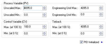
It would be more helpful to see the open-loop step response. This is the CV and PV trends with x and y axis values shown for a manual step change in the CV up until the PV settles, and then down until the PV settles. Also needed are the PV scaling values in the PID block.
__________________
"The greatest enemy of knowledge is not ignorance, it is the illusion of knowledge." -Stephen Hawking |
![]() |
![]() |
#6 |
Member
![]() ![]() Join Date: Apr 2018
Location: Toronto
Posts: 14
|
Thanks for help first:
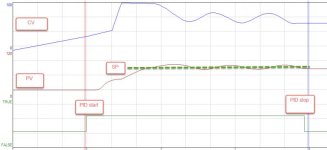
To answer ndzied1 questions: (1) No CV start to ramp after PID start. It is trend type selection result. (2) See new trend diagram attached for time scale (3) PID current loop update time is 0.5 sec (4) PID is running in its own periodic task, period setting is 250ms To answer Mispeld questions: (1) Can't get open-loop step response today because of production (2) In PID block, PV scaling value range ( see attached diagram 2) |
![]() |
![]() |
#7 |
Member
![]() ![]() Join Date: Mar 2018
Location: Ontario
Posts: 16
|
Just wondering
I'm Not an expert at this but I'm wondering...
1) why do you stop the PID after the set point is reached? wouldn't you want to leave it on so that it can reject disturbances and maintain the set point? 2) would Feedforward control be a good choice for this application? if the demanded temperature and flow rate can be known and the input steam temperature can be known then there could be a calculated steam flowrate based on the properties of the heat exchanger system and have the PID just keep out unknown disturbances? |
![]() |
![]() |
#8 |
Member
|
Is there a non-zero deadband setting?
__________________
"The greatest enemy of knowledge is not ignorance, it is the illusion of knowledge." -Stephen Hawking |
![]() |
![]() |
#9 |
Member
|
If the PID instruction unconditional in the periodic task, then loop update time should be equal to the task period (0.25 sec). Changing that will affect the integral action, and is helpful when computing model-based tuning gains.
With the gains you have specified, and the time scale on the trend chart, I am not understanding why the CV is staying constant for the first 10 seconds after the initial proportional action upon starting the loop, which I interpret as switching from manual to auto with an error of about 75 engineering units. That initial action seems about right for the error and proportional gain. It seems as though there is some extra logic manipulating the mode of the loop or the CV immediately after "PID start." I would expect to see the CV continuing to increase at a steady rate due to integral action during the 5 seconds of deadtime, and then increase at a slower rate as the PV starts to come up. Instead, it looks like the loop is suspended until the PV is around half way to set point. Is there any logic that manipulates the .SWM bit with a timer? While deadband shouldn't behave like this, is there a non-zero deadband setting?
__________________
"The greatest enemy of knowledge is not ignorance, it is the illusion of knowledge." -Stephen Hawking |
![]() |
![]() |
#10 |
Member
|
It may not be the Contrologix that does this, I can’t remember. It’s one of the AB PLCs.
Without setting a max CO and min CO, the integral calculation will “run-away” or windup. After passing setpoint, the integral must then wind down and once it’s below, it will wind back up. I don’t suppose you are dipping anything in the tank? If not, then why would integral be needed?
__________________
“Did the Lord say that machines outta take the place of livin’, and what’s the substitute for bread and beans? Do engines get rewarded for their steam?” -John Henry Last edited by seth350; May 17th, 2018 at 09:22 PM. |
![]() |
![]() |
#11 |
Member
|
It looks like there is a dead time.
The gains mean nothing without units. I would look at the controlguru.com website for the formula for tuning temperature systems with dead time.
__________________
"Living is easy with eyes closed, misunderstanding all you see...." Strawberry Fields Forever, John Lennon |
![]() |
![]() |
#12 | |
Member
|
Quote:
In looking at the trend, it might be possible to explain the behavior of the SP, PV, and CV if "PID start" refers to a step change in set point with the loop already in auto, as opposed to a transition from manual to auto (i.e., clearing the .SWM bit). In the former situation, with the loop output (CV) at what looks like zero percent, it is likely the integral term has accumulated some negative control action, though clamped by anti-windup, which must be overcome before contributing to a positive CV movement. Even so, I would not expect a constant CV, at least if CV in the trend is the unmanipulated .CV computed by the PID instruction.
__________________
"The greatest enemy of knowledge is not ignorance, it is the illusion of knowledge." -Stephen Hawking |
|
![]() |
![]() |
#13 |
Member
![]() ![]() Join Date: Apr 2018
Location: Toronto
Posts: 14
|
Thanks for everyone's instruction.
I review the logic, there is timer and pid.maxo limitation logic in current code. When PID is enable/start, a 10 second timer will run and PID.maxo is limited to 30% in 10 second, after timer is done, maxo is changed to 100% Please see attached excel file for PV an CV historian data. Deadband value PID.db is set to 0 in current configuration. PID start/stop is linked with water supply pump status. Supply pump is run by process for 1.5 minutes and then stop for a while and run again and repeat this process for couple of times. Shall I disable the timer and maxo limitation logic? I will increase task pid task periodic time to 500ms to match loop update time After above fix, what procedure shall I follow to identify right Kp and Ki value and allow temperature to reach SP fast(in 1.5 minutes) and without overshoot? |
![]() |
![]() |
#14 |
Member
![]() ![]() Join Date: Sep 2014
Location: NC
Posts: 474
|
I don't have a way to chart that data table, but from your previous chart, I would speed up the loop update to 100ms (no downside). Yes, try disabling the maxo timer logic. Also, one or both of your gains are too high. Try lowering the P gain first.
|
![]() |
![]() |
#15 |
Member
![]() ![]() Join Date: Apr 2018
Location: Toronto
Posts: 14
|
Thanks, Rupej.
Any criteria to decide loop update value? Any benefit to increase to loop update time to 100ms? |
![]() |
![]() |
Bookmarks |
Currently Active Users Viewing This Thread: 1 (0 members and 1 guests) | |
Thread Tools | |
Display Modes | |
|
|
![]() |
||||
Thread | Thread Starter | Forum | Replies | Last Post |
PowerFlex 400 PID Loop for DryCooler Fan / Temperature / Modbus | alexhk | LIVE PLC Questions And Answers | 1 | December 22nd, 2013 09:36 AM |
PID loop update for ML1400 | amitss_sam | LIVE PLC Questions And Answers | 4 | November 2nd, 2012 09:47 AM |
Pressure rate control PID loop | mcafone | LIVE PLC Questions And Answers | 31 | March 26th, 2008 08:10 PM |
Cascade PID Loop | jp1474 | LIVE PLC Questions And Answers | 0 | September 27th, 2006 04:57 PM |
Cascading | Sparky | LIVE PLC Questions And Answers | 24 | February 17th, 2003 12:33 PM |