Unity Pro XL DDT Addressing Problem

siopaoAsado

Member
Join Date
Sep 2011
Location
Manila
Posts
3
Hi all,

I just recently started working with Unity Pro XL and i can say that i am not still used to it. I am at ease working with siemens PLCs but now i am having trouble with unity.

Here's my problem:

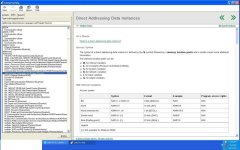
I created an instance DDT (structured variable) which comprises of REALs and BOOLs. However, i dont know how to correctly input the addresses.. Whenever i try to put a %MW to the base tag, the BOOLs also take up the MW address.

How can i correctly address each variable in my DDT?
I attached the screenshots for everyone's reference..

unity.png


I hope someone will help me with this..

Thanks.
 
Keep in mind %MW addresses are Words.

While you can use %MW for discretes and call individual bits such as %MW17.1, it is easier to use %M instead for individual discrete signals.

Hope this helps.
 
Bools are in fact a byte long, the status of the bool is held in the first bit of the bool. From your post I am guessing this is an interface to a hmi device (otherwise there is no real need to set an address) So to reference AlarmHH from an external device the address will be %MW17.0 and alarmH will be at %MW17.8
If you want to use bits then define a word in your ddt and then you can directly access the bits, eg instead of your bools define a word 'StatusBits' then within the program dPIT2000.StatusBits.0 could be used
 
Thank you for all the replies.

I was using the DDTs to map the variables easier, that is why i mixed the bools with the words.

GeoffC, you mean the Bools in my DDT actually accommodates 8 bits? I also read from another forum that it was indeed a byte long and one reccommendation is that either create a separate DDT for BOOLs and another for WORDS or simply create a WORD variable that holds all the BITs needed.

What do you think?

And, i also made a mistake. I need to use REAL not WORDs so i will change the MW with MF.

*another thing i noticed was whenever i change the data type to MD or MF, the number of BOOLs per data type is still 2 considering that it should go to 4 since Double Word or Real is actually 32 bits (32 bits = 4 bytes).
 
Last edited:
It doesn't matter whether the bool is in its own ddt or not, each bool occupies 8 bits (apparently a silly iec rule)
I would put all my bits into a word (use the bit_to_word function)
You can have reals in a ddt that is addressed as %MW, the ddt knows it is a real and assigns 2 mw words for each real
Addressing a ddt as an %MW is the most flexible, I would not bother with %MF. In fact these are just two MW words (eg %MF0 is located in %MW0 and %MW1)
So I would build a ddt with all the required variables of types real, int, dint and word (to hold the bits) and address it as %MW, then use those addresses it generates in your hmi. The hmi knows that a real takes 2 words, an integer 1 word, and a bit takes 1 bit
 
@GeoffC , you are right, BOOL takes a byte ( i thought it is a microprocessor architecture limitation to read and write bits faster !, is it as per IEC ? ) and the most common way to address a DDT is to use %MW only. BOOL elements of DDT will be assigned with MSB byte and LSB byte of same words.

I'm still wondering how to use a EBOOL inside a DDT. This is really required so that I can directly assign physical inputs and outputs to a DDT. But unfortunately, DDT won't support EBOOL data types.

For example, I have 10 motor starters and I create a DDT named DDT - Motor
- Start EBOOL
- Stop EBOOL
- Trip EBOOL
- Ref INT
- Speed INT
Now I can easily create 10 varibales of type 'Motor' like
Pump1 Motor
Pump2 Motor

and assign Pump1.Start to a physical input , %I1

But right now it is not possible as EBOOL are not supported under DDT. Any work around to support this?
 
is memory/scan time a problem for you application where you have to minimize the use of memory as much as possible?
if not, it is always good practice to "transfer" values from physical addresses to memory addresses (especially input values) before "using" them on the program, more so when HMI/SCADA are involved... at least that's how iv been taught. i also find it easier to trace when all physical inputs are located in one section of the program =)
 
Thank you everyone. I decided to use WORD for the group of BOOLs.

GeoffC, I am not aware of the IEC rule making the bool accommodate 8 bits. I used to program siemens PLC. In Step7, when you create a structured tag, the bool accommodates only 1 bit so i was a bit confused in Unity.
 
Bytes vs Bits

I have dealt with having my bools put into an word with a %MW address or just using a direct %M address but I was not sure if there was any difference in efficiency (number of bits). I could put everything into a word like you mentioned, but then I reduce my transparency and readability of my program. I only have a help file or the description to tell you what every bit should be. Or is there a way to get this word to contain bool variables with names?

I'd like to have everything wrapped up in one DDT with names for each variable so I can just call Pump1.StartCmd and Pump1.TmrSP. How much am I shooting myself in the foot if I allow my bools to be read simply as a byte and take up half of a %MW address? Or are %M tags actually more than one bit as well?
 
Also I should add, I always use EBools for addressed data. Other sources have stated that EBools are one Byte anyway. Am I losing anything by using Bools in a DDT rather than an EBool outside of it?
 
When you create a DDT, you can have a word within the structure and then you can name the bits within the word and use those tags within your code. Right click on the WORD and select edit bit rank

Capture.jpg
 
Both Bools and Ebools are 8 bits, not sure if %M are 8 bits but I would guess they are
You do realise that you do not need to address everything in Unity. The only tags that need to be addressed are those that are to be read by an external device using a standard modbus driver (OFS) will directly read tags. You might also locate (give an address) a variable if you need to make it retentative, also Quantum I/O needs to be located
 
Last edited:
Thanks! Yes I only address variables that are talking with the HMI. That's one disadvantage of using a DDT, if it takes all the points my DFB needs to input and output, I will be sending a lot of unneeded information to the HMI. But if i make a DDT for just the HMI tags, am I really helping my variable organization structure that much?
 
Last edited:
You can define the type of any of the variables defined within the DFB (In, out, in/out or public) as your DDT type.
When I make a DFB I would normally include an in/out variable named HMI that would be of a DDT type that only contains the HMI data
 

Similar Topics

Hi all, I'm sure this is a stupidly simple question, but I'm really struggling to find any EFB or similar to do this. I want to map a block of...
Replies
10
Views
3,397
Hello everyone! I am adapting a big Unity project to another smaller application and need to delete a huge amount (thousands) of unused DDTs. The...
Replies
5
Views
3,300
Ok, M3040 with NOC0401 Fanuc Ethernet/IP Slave (20Bytes In/Out) DDT created and defined by DTM as Array of BYTE(0..19) I created my own DDT that...
Replies
3
Views
2,470
Good morning everyone!!! I'm starting to use Vijeo Citect 7.2 with an existant project of Unity Pro. Inside this project we have declared the...
Replies
2
Views
4,694
Hi All Great website, I have found it very useful. Thank you all for your past, present and future replies.:thumb: I have completed my Unity...
Replies
2
Views
5,386
Back
Top Bottom