Potentiometer output tp PLC and HMI

Ltpriyank

Member
Join Date
Sep 2020
Location
Pune
Posts
24
I have been assigned a task to display the output of a potentiometer to a Mitsubishi HMI. SO i have some questions regarding this project
1. While giving potentiometer output to PLC which is Mitsubishi FX3U do I need a signal conditioning card or an analog input module will suffice. I am going to use Mitsubishi FX3U-4AD-ADP.

2. Can I see values from potentiometer dynamically changing on my HMI.

Thanks
 
1) An analog input is good enough, voltage probably. Just make sure the Pot is restricted to the range of the analog input (normally 0-10 or -10 to +10 VDC).


2) Yes, as long as the HMI is looking at a register in the PLC that reflects the analog input the pot is connected to.
 
Yes, you need to program the TO/FROM instructions to get the value from the card. I have only used these but there is another way explained in the manual.
The card uses buffer memories to send/receive data to/from the card these are called BFM registers. Some are used to set the type of analog & other settings others are to read the values or status etc.
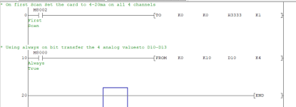
so first of all in the program you do a TO instruction to set the card type for example to set the card to 4-20ma you do a TO instruction sending a Hex value of H3333 this would set all channels to 4-20ma. or you can set different channels to different types i.e. 4-20 0-10v and the resolution etc. see manual.
So on a first scan using M8002 (First scan)
AND M8002 [TO K0 K0 H3333 K1]
K0 This sends to card 0 (first card in expansion)
K0 to BFM 0 (Setting of analog input)
H3333 4-20ma (setting range)
K1 Send 1 word
The FROM instruction reads the analog values
So
AND M8000 (Always on bit) so reads every scan
[FROM K0 K10 D10 K4]
K0 Reads from card 0
K10 Analogue values starting at BFM 10
D10 into D10 to Dxx (so reading all 4 channels to D10 to D13)
K4 Number of channels to read.
Even if you are not needing all channels no problem reading all 4.
Here is the link to the manual
https://www.allied-automation.com/w...X3U-Users-Manual-–-Analog-Control-Edition.pdf
Attached is a program that shows how to set up & get the values from the analogue card.
You need to adapt the values depending where the card fits on the expansion.
There are over 180 buffer memories but only a few need to be used. if you want to scale the values coming back then you can do the maths to scale them.
Also to see the values change on the HMI you just need to add an analogue value field to the display & give it an address i.e. for channel 1 in the example D10
Analogue process.png
 
I do suggest you read the manual fully, unfortunately Japanese manuals are translated to what we call Chinenglish so the descriptions are not always clear. just remember the card position so addressing needs to be right, the Hex values for setting the analogue type etc.
 

Similar Topics

I know of and have used the pot to analog signal condtioners. I am looking for the opposite. I need to convert a 0-5V (or 0-10V, or 4-20MA) to...
Replies
10
Views
2,821
Hello everybody, I need to adapt and automate one old machine and for that case I need some kind of resistive variable output (preferable from 0...
Replies
6
Views
3,565
Hello, We are currently working on a project that involves connecting a linear potentiometer to our Beckhoff PLC. After researching, we...
Replies
2
Views
197
Wondering if anyone has dealt with this and had any idea what the wiring would be? Box says "Platine R/I-Wandler TL 42543 rechtsoffnend. I have...
Replies
5
Views
1,579
Hi folks, I'm doing a valve positioning system (new plc replacing old discrete instrumentation), the old system has position feedback from valves...
Replies
7
Views
2,665
Back
Top Bottom