You are not registered yet. Please click here to register!


plc storereviewsdownloads
This board is for PLC Related Q&A ONLY. Please DON'T use it for advertising, etc.
 
Try our online PLC Simulator- FREE.  Click here now to try it.

New Here? Please read this important info!!!


Go Back   PLCS.net - Interactive Q & A > PLCS.net - Interactive Q & A > LIVE PLC Questions And Answers

Reply
 
Thread Tools Display Modes
Old May 24th, 2018, 06:33 PM   #16
Robb B
Lifetime Supporting Member
Canada

Robb B is offline
 
Join Date: Feb 2011
Location: BC, Canuckistan
Posts: 332
I misread the values,

motion group coarse update period is 32ms.

scan times average 500us, though max time was 5111us.

The servo update period is 2000 us.

The valve response time is around 240ms for a zero to 100% response.

I'm assuming that us means microseconds.

The controller is not the slowest thing in the loop by a large margin.
  Reply With Quote
Old May 24th, 2018, 07:54 PM   #17
Peter Nachtwey
Member
St Kitts and Nevis

Peter Nachtwey is offline
 
Peter Nachtwey's Avatar
 
Join Date: Apr 2002
Location: No income tax, no capital gains tax. Freedom!
Posts: 8,274
Quote:
Originally Posted by Robb B View Post
I misread the values,

motion group coarse update period is 32ms.
I am not familiar with how the group update works. Seems slow.

Quote:
scan times average 500us, though max time was 5111us.
If this is the PLC scan time then no problem

Quote:
The servo update period is 2000 us.
This is the coarse update 2000 microsecond or 2 ms. This is OK considering the valve is so slow..
Quote:

The valve response time is around 240ms for a zero to 100% response.
The valve is junk. You need to replace it.
You need finer resolution.
__________________
"Living is easy with eyes closed, misunderstanding all you see...." Strawberry Fields Forever, John Lennon
  Reply With Quote
Old February 1st, 2023, 03:27 PM   #18
Robb B
Lifetime Supporting Member
Canada

Robb B is offline
 
Join Date: Feb 2011
Location: BC, Canuckistan
Posts: 332
Back from the dead...

New valve installed: 4WRPEH 10 C4 B100L-20/G24K0/A1M I believe this one should be appropriate for motion control. I am in the process of trying to get a better encoder.

Manual: https://airlinemedia.airlinehyd.com/...28_11_2013.pdf

I think the pertinent details are:
Hysteresis <0.2%
Actuating time for signal step 0...100 % ms ≦ 25

All parameters are the same as before, I am wondering if/what parameters should be changed? Should I do a "Tune"? I am still seeing an overshoot in position at the end of each travel direction, as well as intermittent oscillation when stopping from a manual move (using MAM and MAS). Any suggestions? I will try to add a fresh trend later today.

Last edited by Robb B; February 1st, 2023 at 03:34 PM.
  Reply With Quote
Old February 1st, 2023, 05:01 PM   #19
Peter Nachtwey
Member
St Kitts and Nevis

Peter Nachtwey is offline
 
Peter Nachtwey's Avatar
 
Join Date: Apr 2002
Location: No income tax, no capital gains tax. Freedom!
Posts: 8,274
The valve should be good. What you need to do is a manual job using the direct output command. This will show if the mechanics are tight. Also, there better not be hose between the valve and the cylinder. Hose between the valve and the cylinder will act like a spring.

It is cold but clear down here. I bet it is colder there.
__________________
"Living is easy with eyes closed, misunderstanding all you see...." Strawberry Fields Forever, John Lennon
  Reply With Quote
Old February 2nd, 2023, 10:48 AM   #20
Robb B
Lifetime Supporting Member
Canada

Robb B is offline
 
Join Date: Feb 2011
Location: BC, Canuckistan
Posts: 332
Quote:
Originally Posted by Peter Nachtwey View Post
The valve should be good. What you need to do is a manual job using the direct output command. This will show if the mechanics are tight. Also, there better not be hose between the valve and the cylinder. Hose between the valve and the cylinder will act like a spring.

It is cold but clear down here. I bet it is colder there.
I think it is hard lines all the way, will find out for sure later. The valve drives a hydraulic motor which is chained to the hoist. You can see the encoder end of the chain at the far end of the hoist in the picture.

-3 this morning, and threatening more snow.
Attached Images
File Type: jpg Stacker hoist.jpg (191.7 KB, 80 views)
  Reply With Quote
Old February 2nd, 2023, 12:08 PM   #21
Peter Nachtwey
Member
St Kitts and Nevis

Peter Nachtwey is offline
 
Peter Nachtwey's Avatar
 
Join Date: Apr 2002
Location: No income tax, no capital gains tax. Freedom!
Posts: 8,274
Quote:
I think it is hard lines all the way, will find out for sure later. The valve drives a hydraulic motor which is chained to the hoist. You can see the encoder end of the chain at the far end of the hoist in the picture.

-3 this morning, and threatening more snow.
is there slop in the chain? Also, hydraulic motors have a lot of stiction. You may need to use the dead band eliminator to keep from rocking back and forth.

It is cold here too. 28 deg F and I need to work on my camper's back up camera.

I see hose. Too much hose.
On top of that the speed of sound in hydraulic oil is about 1 ft per millisecond. If there is 20 ft of hose between the valve and the cylinder, the dead time will be about 5 milliseconds. That means that it will take 5 milliseconds for what ever the valve does to get to the piston.

Quote:
The controller is not the slowest thing in the loop by a large margin.
No kidding. Again, getting a trend in direct output mode will tell a lot. Create pens for actual position and control output.
__________________
"Living is easy with eyes closed, misunderstanding all you see...." Strawberry Fields Forever, John Lennon
  Reply With Quote
Old February 2nd, 2023, 12:35 PM   #22
Robb B
Lifetime Supporting Member
Canada

Robb B is offline
 
Join Date: Feb 2011
Location: BC, Canuckistan
Posts: 332
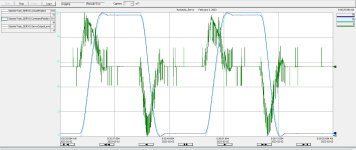
The hoses are for the hoist hydraulics, up/down, clamp in/out. The motor is up in the rafters, pretty sure it's hard line the whole way. The millwright says the chain is "fairly tight". The hardline run is more than 20ft from the valve to the motor, probably closer to 45 ft. Attached trend from this morning.
Attached Images
File Type: jpg Motion cycle auto 2023 02 02.jpg (195.7 KB, 73 views)

Last edited by Robb B; February 2nd, 2023 at 12:46 PM. Reason: New trend
  Reply With Quote
Old February 2nd, 2023, 01:05 PM   #23
Peter Nachtwey
Member
St Kitts and Nevis

Peter Nachtwey is offline
 
Peter Nachtwey's Avatar
 
Join Date: Apr 2002
Location: No income tax, no capital gains tax. Freedom!
Posts: 8,274
OK, the trend is helpful but closed loop control not open loop.
Do you see the spikes in the control output? That happens because your feedback is too coarse. You don't have enough pulses per inch or turn of your hydraulic motor.

Notice the actual position seems to lead the target position. It looks like you are using feedforwards but they are a little high.

Look at about 9:35:31
What confuses me is that you can see the target position move to a new position and stop. The actual position does an OK job of tracking the target but when the target position is reached, the actual position is not overshooting. It is being drawn back

Look at the vertical line a 9:35:37.694
but the control output doesn't seem to respond to the error between the target and actual position. That is a huge steady state error at the set point. It doesn't look like the integrator is being used or the control output would be winding up during the time it is stopped. It doesn't look there us much proportional gain being used. Look at the control output when at rest when it is after a positive move and a negative move. The errors have different signs. The control output should be different during these periods.
It looks like no proportional gain is used at all or the closed loop gains are set to 0 after the target position reaches the command position.

BTW, guys. An experienced person can can tell a lot from a trend or plot.
__________________
"Living is easy with eyes closed, misunderstanding all you see...." Strawberry Fields Forever, John Lennon

Last edited by Peter Nachtwey; February 2nd, 2023 at 01:08 PM.
  Reply With Quote
Old February 2nd, 2023, 02:41 PM   #24
Robb B
Lifetime Supporting Member
Canada

Robb B is offline
 
Join Date: Feb 2011
Location: BC, Canuckistan
Posts: 332
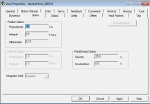
Peter, very helpful. The Gains tab has the following configuration as per picture. In addition, there is a Limits tab which has:
1. Position Error Tolerance: 20 inches (seems really high to me?)
2. Position Lock Tolerance: 1 inch (which probably accounts for the difference in position when not moving)

There is also an Output tab which has "Velocity Scaling" at 10% / (inches/s)

Rockwells manual define these items, but don't give any insight as to how they affect the controls, or I'm not sufficiently versed. Probably the latter.

Thanks again for your insights, Peter. Invaluable!
Attached Images
File Type: jpg Stacker Gains Configuration 2023 02 02.jpg (62.7 KB, 67 views)
  Reply With Quote
Old February 2nd, 2023, 04:34 PM   #25
Robb B
Lifetime Supporting Member
Canada

Robb B is offline
 
Join Date: Feb 2011
Location: BC, Canuckistan
Posts: 332
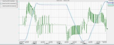
I was able to capture a "manual move" of the hoist, the logic uses Motion Axis Move and Motion Axis Stop (MAM and MAS) instructions, same as in automatic, but the values for speed, acceleration, etc are different. Interesting to see the oscillation in position there, does that hint at the stiction in the hydraulic motor? I don't want to derail the original issues, but it's likely they are related, no?

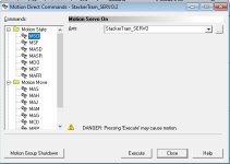
When you say open loop control, are you referring to using the axis commands to directly move the hoist, without any logic?
Attached Images
File Type: jpg Motion cycle manual 2023 02 02.jpg (479.7 KB, 14 views)
File Type: jpg Motion Direct Commands.jpg (52.7 KB, 12 views)
  Reply With Quote
Old February 2nd, 2023, 10:23 PM   #26
Peter Nachtwey
Member
St Kitts and Nevis

Peter Nachtwey is offline
 
Peter Nachtwey's Avatar
 
Join Date: Apr 2002
Location: No income tax, no capital gains tax. Freedom!
Posts: 8,274
A direct output command would not have the spikes in the control output.

A direct output command simply sends a voltage to the valve. You need to be fast to turn the voltage back to 0 to keep it from running into something.

The spikes are caused by the **** poor resolution of the encoder and I see you are using the derivative gain. Don't use the derivative gain. If your really need to I think the Rockwell software has an output filter feature that will reduce the spikes in the output.

The big thing I see is that no matter which direction you move, you don't get to the command position and the even though the direction of the error changes, the control output is still the same. It looks like the M02AS is making no attempt to get in position with the parameter you have.

I have never liked the way Rockwell scaled their gains. It isn't intuitive.
__________________
"Living is easy with eyes closed, misunderstanding all you see...." Strawberry Fields Forever, John Lennon
  Reply With Quote
Old February 3rd, 2023, 10:50 AM   #27
Robb B
Lifetime Supporting Member
Canada

Robb B is offline
 
Join Date: Feb 2011
Location: BC, Canuckistan
Posts: 332
Quote:
Originally Posted by Peter Nachtwey View Post
A direct output command would not have the spikes in the control output.

A direct output command simply sends a voltage to the valve. You need to be fast to turn the voltage back to 0 to keep it from running into something.

The spikes are caused by the **** poor resolution of the encoder and I see you are using the derivative gain. Don't use the derivative gain. If your really need to I think the Rockwell software has an output filter feature that will reduce the spikes in the output.

The big thing I see is that no matter which direction you move, you don't get to the command position and the even though the direction of the error changes, the control output is still the same. It looks like the M02AS is making no attempt to get in position with the parameter you have.

I have never liked the way Rockwell scaled their gains. It isn't intuitive.
Next time we run timbers that don't use the stacker I will run some direct commands and trend it. Millwright's also going to verify hardlines all the way to the motor (he thinks some might be hose that got put in when a line failed), as well as backlash (hysteresis?) at the final drive elements (chain, motor, sprocket, etc). Researching new encoder as well.
  Reply With Quote
Old February 3rd, 2023, 03:31 PM   #28
kamenges
Member
United States

kamenges is offline
 
kamenges's Avatar
 
Join Date: Nov 2002
Location: Brillion, WI
Posts: 4,292
Quote:
Originally posted by Peter Nachtwey:

The big thing I see is that no matter which direction you move, you don't get to the command position...
I wouldn't get too hung up on that, Peter. That looks to me like a trend scaling issue. You notice how all three of the traces conveniently hit both the top and the bottom of the trend window? I suspect that the trend is set up to auto scale. So the actual and command position traces are not on the same scale. If you look at the window in the upper right corner of the trend from a few post back you will see that both the commanded and actual position values are at 16.

Robb B, go into the Pens tab of your trend and set the min and max values for each of the pens you have for the expected range of the value plus 10%. But make sure you set the min and max of both the command and actual positions to the same values. Then on the Y-axis tab in trend set-up, select the Preset min/max option in the upper left corner and the "Each pen on independent scale" selection in the scale options in the lower right. this will make the graph make more sense.

Keith

Keith
  Reply With Quote
Old February 3rd, 2023, 07:20 PM   #29
Peter Nachtwey
Member
St Kitts and Nevis

Peter Nachtwey is offline
 
Peter Nachtwey's Avatar
 
Join Date: Apr 2002
Location: No income tax, no capital gains tax. Freedom!
Posts: 8,274
So the target and actual positions are not on the same scale? The tracking looks good when moving.
__________________
"Living is easy with eyes closed, misunderstanding all you see...." Strawberry Fields Forever, John Lennon
  Reply With Quote
Old February 5th, 2023, 06:26 AM   #30
MaxK
Member
Czech_Republic

MaxK is offline
 
Join Date: Jul 2022
Location: FrozenHell
Posts: 216
It would be very interesting to see also the control curve, because the nature of the noise modes in the valve position signal is not clear.
  Reply With Quote
Reply
Jump to Live PLC Question and Answer Forum


Currently Active Users Viewing This Thread: 1 (0 members and 1 guests)
 
Thread Tools
Display Modes

Posting Rules
You may not post new threads
You may not post replies
You may not post attachments
You may not edit your posts

BB code is On
Smilies are On
[IMG] code is On
HTML code is Off

Forum Jump


All times are GMT -4. The time now is 02:44 PM.


.