4-20mA loop grounding

Jenny8711

Member
Join Date
May 2020
Location
London
Posts
10
Hi all,

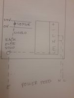
I'm connecting several 4-20mA sensors together in parallel (only one shown below) The enclosure is ABS plastic with metal backplate

DAQ could be powered from 24 rail or separate PSU (optional)

I am wondering where exactly to ground the shield of the sensors? (only grounding at instrumentation end, not sensor end)

Many posts have talked about grounding at common/earth etc, would this be at the 0V rail? For all sensors? Can sensors and power supply be grounded together?

Any help and advice gratefully received

Thank you
 

Attachments

  • circuit.png
    circuit.png
    18.2 KB · Views: 33
Last edited:
Your diagram shows 0V, but no earth ground () location. The backplate would normally be bonded with a wire to an earth ground (green or bare copper wire), mostly for safety reasons. The shields are normally then tied to this ground. They can also just be bonded together and left floating as well, but typical to bond it to the panel ground. That being said, if the panel has a power feed coming in, then hopefully the backplate is bonded to an earth grounding conductor, otherwise, a ground rod or similar grounding path should be established. The whole point is to dissipate any induced voltage on the shield to ground (earth), and in one place only. If not, you create a ground loop and the current moving through it could induce a voltage on the wires inside. Now, sometimes you will see engineers bond the 0V and ground, but that would typically be done at the power supply. If this is done, then tying it to 0V is essentially the same thing, but you need to understand if that has been done or not.
 
OK thank you

So I understand for my own learning, do you mean:

Power feed live and neutral to PSU
Power feed earth to backplate stud
Backplate stud connects to shield cables and also PSU earth

As attached diagram

Your help is much appreciated!

Thanks
 

Attachments

  • panel-earthing.jpg
    panel-earthing.jpg
    49.9 KB · Views: 26
OK thank you

So I understand for my own learning, do you mean:

Power feed live and neutral to PSU
Power feed earth to backplate stud
Backplate stud connects to shield cables and also PSU earth

As attached diagram

Your help is much appreciated!

Thanks
Yes, exactly like you have it drawn. The entire point is to dissipate any voltage you get on the shield to earth ground. Now, keep in mind, only do this on the Control Panel side. On the sensor side, cut and tape the shield. If you stick to this method, you likely will never run into any issues.
 
Yes, exactly like you have it drawn. The entire point is to dissipate any voltage you get on the shield to earth ground. Now, keep in mind, only do this on the Control Panel side. On the sensor side, cut and tape the shield. If you stick to this method, you likely will never run into any issues.
Thank you
 

Similar Topics

Hi all, I need to send a 4-20mA signal from a PLC (ICLinks Everest) to a paperless chart recorder (Endress and Hauser RSG30) and I'm having a...
Replies
7
Views
2,262
I am connecting a 4-20mA signal from an RTD transmitter to an ABB ACH 550 drive. My sensor is an ACI RTD Freezer Transmitter with a range of...
Replies
2
Views
1,757
Last night I ran into three drives on the same speed control 4-20. I had never seen this before and thought multiple devices would cause...
Replies
8
Views
3,765
I'm probably going to be called stupid for asking this. I have only ever used 2 wire sensors. we would connect one wire to 24 dc+ and the return...
Replies
41
Views
7,231
Greetings, Sorry to sound like such a noob...but I am.... I have a conveyor belt scale integrator that I am trying to get to communicate with a...
Replies
5
Views
3,003
Back
Top Bottom