AB-PLC5 to AB-ControlLogix

Parras89

Member
Join Date
Mar 2022
Location
wyoming
Posts
2
Hello,

I'm starting in the PLC world, mostly doing troubleshooting and little changes to programs for the last year and a half, also have done a couple of training with AB so far.

We have a system that was originally PLC5, something failed some time ago and previous engineer replaced the processor in a hurry, leaving the system with a 1756-I55 processor and a 1756-DHRIO connected to the old 1771 chassis trough a remote I/o adapter.

The best to do, in my opinion; will be to update it all to 1756 modules, since parts are just going to be more scarce as time passes, and want to avoid the old chassis or modules failing and the need to do the same upgrade in emergency mode.

I have the option to contract this out but I would like to learn how to do it by myself instead and since no one is stressing me out to get this done by a certain date.

What would you think will be the best and quickest approach/way to achieve this upgrade?

Thanks.
 
Welcome to the PLCTalk forum community !

I agree that your system sounds like a good upgrade and learning opportunity.

If absolute minimum downtime is your goal, there are retrofit kits available from Rockwell that bolt in place of the 1771 chassis and have swingarm adapters to 1756 I/O modules.

But for a single chassis system, I would probably choose to spend the labor and time on re-wiring the swingarms.

More questions and suggestions:


Do a thorough inventory of the I/O modules that are installed in the chassis and select equivalents from the 1756 family.

Is the 1756-DHRIO also used for DH+ communications ? If so, you may wish to leave it in place and will need another empty slot for an EtherNet/IP bridge module.

Check the firmware revision of the 1756-L55 controller. It's possible that it is old enough not to support EtherNet/IP I/O scanning. In general, those controllers support up to v16 firmware, so if you upgrade you will also need RSLogix 5000 v16.

I don't recommend using ControlNet for this CPU -> Chassis bridge unless you are already using it extensively. EtherNet/IP is equivalent or superior for most purposes.

If there are analog modules in the I/O chassis, search your program for MSG instructions used for Block Transfer purposes through the 1756-DHRIO. Document and make sure you understand the channel configurations so you can duplicate them on a 1756 series analog module.
 
...We have a system that was originally PLC5, something failed some time ago and previous engineer replaced the processor in a hurry, leaving the system with a 1756-I55 processor and a 1756-DHRIO connected to the old 1771 chassis trough a remote I/o adapter.

They already have their CLX CPU. There is no need to convert any program. He is trying to convert the 1771 style I/O and chassis hardware to newer CLX hardware.

OG
 
Addresses Convertion

Guys,

Thanks for the answers, What I want to do is get rid of the old 1771 and get a bigger chassis for getting all the new I/O modules in the same chassis as the controller. Is there a way to get the tags converted from the old modules' addresses to the new modules addresses not manually? I think I saw someone talking about having an excel spreadsheet and assigning there the new addresses for the tags and then updating all into the controller from the spreadsheet, is this doable or I just misunderstood the whole thing?


I though I answered this last week but it did not went trough.

IMG_5490_LI.jpg
 
Proceed with caution

Thank you for the detail and context !

Because this is a small project, in my opinion you should do the I/O address conversions "by hand", either entirely in RSLogix 5000 or using some export/text edit/import steps in *.L5K format.

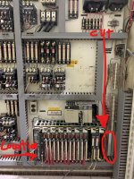
My familiarity with 1771 I/O has faded some, so I'd like to encourage you to examine the modules carefully. Those look like ordinary 1771-IAD and 1771-OAD sixteen-point modules but there are so many red wires terminated on them that I wonder if they're the 32-point modules instead. A quick look at the number of numbered LED indicators at the top will tell you.

I genuinely can't tell if those modules on the right are old 8-point AC inputs (1771-IA). The nine red indicators look correct for the PLC-2 era 8-point inputs, but the label on top of those was red or orange. The wiring to them looks like analog wiring, but they're definitely not 1771-IFE or -OFE modules.

Clearly this system has had a long service life. The wiring is still relatively tidy, but the not-even-finger-safe energized 480V and 120V terminals make me twitch a little. Do yourself a favor and sit a safe distance away from that cabinet if you work on it while it's energized.

Also, I hope those IP address labels are long-obsolete. While it's probably not your problem to solve right now, whoever set this system up used "public" Internet addresses, instead of a private IP subnet. The address on that sticker belongs to a university in Barcelona !

The automated or semi-automated conversion of PLC-5 logic to ControlLogix isn't as smooth and error-free as you might hope. Many users choose to take their time and convert to native Logix tags with descriptive names instead of doing a lot of mapping and emulating.

I assume you've already looked at the swingarm retrofit kits that bolt in place and would let you not disturb the terminations.

There's also some helpful tools built into Integrated Architecture Builder for choosing 1756 products to replace 1771 products:

https://www.youtube.com/watch?v=3VrcZifvf50

But your first few steps should definitely involve getting a detailed inventory of the 1771 modules that are actually installed there.

Is that the only 1771 chassis controlled by that ControlLogix CPU, or are there others ?
 
My familiarity with 1771 I/O has faded some, so I'd like to encourage you to examine the modules carefully. Those look like ordinary 1771-IAD and 1771-OAD sixteen-point modules but there are so many red wires terminated on them that I wonder if they're the 32-point modules instead. A quick look at the number of numbered LED indicators at the top will tell you.

I genuinely can't tell if those modules on the right are old 8-point AC inputs (1771-IA). The nine red indicators look correct for the PLC-2 era 8-point inputs, but the label on top of those was red or orange. The wiring to them looks like analog wiring, but they're definitely not 1771-IFE or -OFE modules.

It looks like two columns of indicators instead of four. And they all have ACTIVE indicators, so I'm guessing these are 16 point input and output modules. The 32-point modules didn't have an ACTIVE indicator. What's getting me is that the labels are wider on some than on others. So it looks like there are two types of input modules and two types of outputs. Or possibly they changed the size of the labels and we just are seeing older and newer modules.

As you mentioned, those two modules on the far right are a head scratcher. The wiring looks like they would be analog. but I don't recall the analog modules having all those indicators. I only recall a Fault and a Run indicator. But, it's been ages. I'm wondering if those are maybe something unusual like TTL or BCD modules. That grayish label I just don't remember.

OG
 
Good eye on the ACTIVE indicator, OG. I thought I was only seeing two rows of point status LEDs (00-07, 10-17) but wasn't sure.

The different width labels were also throwing me, but it's certainly possible that A-B changed the labels a little in the 1980's. The color codes have remained consistent for decades.

Folks who are accustomed to being able to "drill down" in a ControlLogix backplane to communicate directly with I/O modules, or even remember clicking on "Read IO" in RSLogix 500 to read the module ID codes to populate the IO Configuration tree probably don't remember that very little of that was available in the PLC-5.

The PLC-5 did have a decent "Autoscan" feature for Remote I/O networks, but really all it did was read the node numbers and their sizes, and maybe could tell the difference between a 1771-ASB and a 1794-ASB. It couldn't tell what was physically installed in the chassis.

So when you're going to convert an old PLC-5 and the prints and notes have been lost to the ages, you need to do some direct examination. Bring notepaper and a pen and a phone or digital camera. If you can do it during a scheduled shutdown, pull out the modules and get all the part numbers off the sides and note any configuration jumpers.
 
Just ran across a picture of the 1771-OG module. It is their TTL output module and it does have a gray label. So I think that might be the culprit for those last two modules.

OG

TTL Output.png
 
Last edited:
To my knowledge, all the PLC-2 era 8-point modules looked like that.

The color of the labels is supposed to be an at-a-glance reference.

Off the top of my head

Orange = AC Out
Red = AC In
Brown = Relay Out
Green = DC Out
Blue = DC In
Pink = Analog In
Yellow = Analog Out

Evidently Gray = TTL.

But there's nothing quite so good as a direct inspection with a Mark-1, Rev-1 eyeball.
 

Similar Topics

Hello, I am currently converting a project from PLC5 to ControlLogix. I have migrated the program from Logix5 to Logix5000 and any Block Transfer...
Replies
4
Views
3,349
Hello, Today I am trying to figure out the best way to write from controllogix to a plc5 only on change. The situation: - Migrated a Winview...
Replies
3
Views
2,114
We have a controllogix setup with 3 racks, and 14 racks of PLC5 using RIO cards. Here is my question. One of the PLC5 racks has a...
Replies
8
Views
1,722
In one of my project, end-user wants to connect Controllogix 1756 IO's with PLC 5/40E controller on DH+ protocol. 1756 DHRIO card is installed in...
Replies
9
Views
6,720
Hey all, I've got a migrated PLC5 program running well on a new CLX processor. As you surely know, tags like B3:0/0 convert over to B3[0].0 and...
Replies
4
Views
3,216
Back
Top Bottom