ABB ACQ580 Ethernet/IP communications to MicroLogix

mylespetro

Member
Join Date
Dec 2015
Location
NS
Posts
740
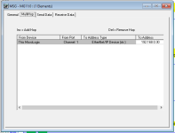
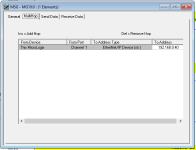
Hey everyone, working with an ABB drive for the first time, and I've found the sample programming that ABB provides for communicating with a MicroLogix PLC over Ethernet/IP using one of their communication adapters. Just noticed something in the program that doesn't really make sense to me, it uses explicit messaging to read and write to the drive, but the IP address in the MultiHop tab is different between the two messages, despite them being intended for the same drive. I've attached pictures below, MG10:0 is the write message to the drive and MG11:0 is the read. The adapter that's been specified for the project is a FENA-21 adapter. I don't have the drive available for a bench test unfortunately.


For reference, MG10:0 has a MultiHop address of 192.168.0.40 and MG11:0 has a MultiHop address of 192.168.0.30. Just curious if there's something I'm missing or if this is potentially a typo? I've attached the zipped .RSS file as it comes from the ABB website as well.


As a secondary question, is the ACQ580 drive essentially the same as the ACS580 drive with some water/wastewater specific functionality? Or are they completely different? As I said at the start of the post, this is my first experience with ABB drives, however I do know that the ACS series is pretty common.


Thanks in advance!
Capture1.PNG Capture2.PNG
 

Attachments

  • FENA_RETA_RSL500_SAMPLE_PROGRAM.zip
    10.3 KB · Views: 14
Hey everyone, finally got around to commissioning this project almost a year later, just wanted to provide an update and ask a couple more questions.

It would appear that the different IP addresses was indeed a typo, I was able to establish communications between the PLC and the drives by using the same IP address for the read and write messages. For reference, the drives are using a FENA-21 adapter to allow for Ethernet/IP comms.

I was however unable to get the drive status word present in the PLC to match what the drive status word of the drive itself was showing. In the PLC, the word had a value of 784 decimal, or 0000 0011 0001 0000 in binary. However, the status word in the drive was pretty different - I unfortunately didn't think to write down what it was, but I believe it was presented in hex, and you could drill down to see the binary value. It was something like 1033 hex (again, likely different in actuality, but close), or 0001 0000 0011 0011 in binary.

Just looking to see if anyone has ever used a FENA-21 adapter for Ethernet/IP comms with a MicroLogix 1400 (or any PLC really), and how to go about configuring the data that comes back to the PLC over the message instructions. I'm wondering if the status word on the drive is separate from the status word on the adapter, and it needs to be configured on the adapter to pull the values of certain parameters out or something along those lines. The manual is a little hard to wrap my head around, but I have tried to follow along as best as I could, unfortunately I couldn't quite figure out if I had screwed something up.

I'll try and get some screenshots of my message configurations and add another reply with those.
 
three out of four of those nibbles suggest a byte swap has occurred, but that does not make sense if this is Ethernet/IP.


Can you get the actual expected and measured status words. It seems odd that you can read the bits but that they are wrong.
 
three out of four of those nibbles suggest a byte swap has occurred, but that does not make sense if this is Ethernet/IP.


Can you get the actual expected and measured status words. It seems odd that you can read the bits but that they are wrong.

I was thinking something like that may have happened, I've run into that on a Siemens Milltronics belt scale before, which I believe was also Ethernet/IP. Again, the hex word I posted was going by memory and I don't believe it to be correct. I'll try and get an actual picture of the status word if I'm onsite in the next few days.

The adapter is currently configured for an ODVA profile, and the only other option is ABB Enhanced Drive profile or something along those lines.
 
I was thinking something like that may have happened, I've run into that on a Siemens Milltronics belt scale before, which I believe was also Ethernet/IP.


Perhaps we should qualify "Ethernet/IP" to be "correctly implemented Ethernet/IP."

I.e. Caveat Emptor.
 
The adapter is currently configured for an ODVA profile, and the only other option is ABB Enhanced Drive profile or something along those lines.

It's entirely possible that those two profiles present status bits in a different order, or that whatever you view on the drive's HMI is ABB-specific.

ABB has a long history and wide variety of network communication modules, so they're actually one of the best resources for perspective on ODVA compliant profiles versus proprietary ones !

An excellent document:

https://library.e.abb.com/public/4814c384e83d13f385257c9a0050c30b/LVD-PNTG03U-EN_REVE_WEB.pdf

Page 8 shows the Status Word for an ACS800 drive. A simplified summary:

0 RDY_ON
1 RDY_RUN
2 RDY_REF
3 TRIPPED
4 OFF_2_STA
5 OFF_3_STA
6 SWC_ON_INHIB
7 ALARM
8 AT_SETPOINT
9 REMOTE
10 ABOVE_LIMIT
11 EXT CTRL LOC
12 EXT RUN ENABLE
13 B13 Pointer Value
14 B14 Pointer Value
15 Comms Error

Compare that to the ODVA AC/DC Basic Drive Profile status word:

0 Faulted
1 Warning
2 Running Fwd
3 Running Rev
4 Ready
5 Controlled from Network
6 Reference from Network
7 At Reference
8-15 Drive State

There is... a lot more. If you can share the exact way that the MicroLogix 1400 MSG instructions were addressing the ABB drive, then folks might be able to point to the relevant sections of the FENA-21 or ACQ580 documentation.
 
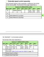
So I'm looking at the manual for the FENA adapter, and I believe that I'm configured for the "Extended Speed Control" assembly (Instances 21 and 71) based on what I have entered in the MSG configuration - Instance 21 (decimal) for the write, and Instance 71 (decimal) for the read. This is a bit more self explanatory, as it lists the bytes (and bits) of the data to and from the drive, but I was expecting two 16-bit integers, not four bytes (8 bits).

For example, if I were reading the drive status into N21:0, with a "Size in Bytes" of 4, would these write into N21:0-8, N21:9-15, N22:0-8 and N22:0-15? Or would it write one byte into the first 8 bits of N21, N22, N23 and N24?

I'll attach a screenshot of the data layout from the manual, I feel like I've almost got it figured out but this is my first time having to get this involved with instances/assemblies in explicit messaging, so there's probably some data manipulation that I don't know how to do.

Just to reiterate, I did use ABB's canned messaging logic specifically for RSLogix 500/MicroLogix controllers.

ABB FENA ODVA EIP.PNG
 
It's entirely possible that those two profiles present status bits in a different order, or that whatever you view on the drive's HMI is ABB-specific.

ABB has a long history and wide variety of network communication modules, so they're actually one of the best resources for perspective on ODVA compliant profiles versus proprietary ones !

An excellent document:

https://library.e.abb.com/public/4814c384e83d13f385257c9a0050c30b/LVD-PNTG03U-EN_REVE_WEB.pdf

Page 8 shows the Status Word for an ACS800 drive. A simplified summary:

0 RDY_ON
1 RDY_RUN
2 RDY_REF
3 TRIPPED
4 OFF_2_STA
5 OFF_3_STA
6 SWC_ON_INHIB
7 ALARM
8 AT_SETPOINT
9 REMOTE
10 ABOVE_LIMIT
11 EXT CTRL LOC
12 EXT RUN ENABLE
13 B13 Pointer Value
14 B14 Pointer Value
15 Comms Error

Compare that to the ODVA AC/DC Basic Drive Profile status word:

0 Faulted
1 Warning
2 Running Fwd
3 Running Rev
4 Ready
5 Controlled from Network
6 Reference from Network
7 At Reference
8-15 Drive State

There is... a lot more. If you can share the exact way that the MicroLogix 1400 MSG instructions were addressing the ABB drive, then folks might be able to point to the relevant sections of the FENA-21 or ACQ580 documentation.

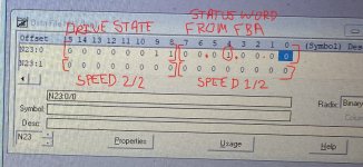
Hey Ken, you must have posted while I was typing out my reply just now. Your status bit layout seems to match with what's shown in my screenshot. If I look at the status word value that I was reading on the PLC with this reference, it seems like it made sense for the most part:

Bits:

0-0 (NOT faulted)
1-0 (NOT warning)
2-0 (NOT running fwd)
3-0 (NOT running rev)
4-1 (Ready)
5-0 (NOT Ctrl from net)
6-0 (NOT Ref from net)
7-0 (NOT At reference)

Byte 1 (bits 8-15) - Drive state:
8-xxx0xxx 1
9-1
10-xxx1xxx 0
11-0
12-0
13-0
14-0
15-0

I would have to check what a value of 6 (? - I'm assuming that the value of this byte is 6 and not actually what the value of the equivalent 16-bit integer would be) means for the drive state.

EDIT: I just checked the Drive State reference, and it says a value of 6 would be "Fault Stop". This leads me to believe that bit 0 is a 1 when the drive is in a good state perhaps? But if that's the case, I wouldn't expect the Ready bit to be a 1...

EDIT 2: Just realized I wrote the bits down wrong, bits 8 and 9 were 1, not 9 and 10. That would make the Drive Status code 3, which means Ready.
 
Last edited:
Hate to triple post, but I think I'm starting to realize that I'm getting the proper data in/out of the drive, I just wasn't aware of how the data structure works. One thing of note is that we're not actually doing any control TO the drive over the network - controlling through hardwired I/O - we're only using the network for feedback/status from the drive.

Thanks Ken and drbitboy, hopefully I'll be able to get it figured out at this point.
 
Compare that to the ODVA AC/DC Basic Drive Profile status word:

0 Faulted
1 Warning
2 Running Fwd
3 Running Rev
4 Ready
5 Controlled from Network
6 Reference from Network
7 At Reference
8-15 Drive State

.

You may have moved beyond this, but FWIW, I used the FENA-21 with a CompactLogix. Instance 21/71 Extended Speed Control, as you are using. I got 2 INT's in and 2 INT's out and no swapping or Big Little Endian stuff to deal with. The first INT in matches up with what Ken posted. The 2nd INT in was speed reference.
 
You may have moved beyond this, but FWIW, I used the FENA-21 with a CompactLogix. Instance 21/71 Extended Speed Control, as you are using. I got 2 INT's in and 2 INT's out and no swapping or Big Little Endian stuff to deal with. The first INT in matches up with what Ken posted. The 2nd INT in was speed reference.

Yes, it looks like I’m getting two INTs in and out, the second INT on the write being speed reference, and the second INT on the read being actual speed feedback. Thanks for the confirmation!
 
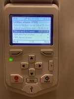
Just another little update, almost everything looks good on my end, the only little thing I noticed is that the "Status word to master" shown under the fieldbus adapter (FBA) is showing 00.00.00.00 (ditto for "Control word from master," but this does happen to be the case - hardwired control so nothing is being written to the drive), whereas the data showing in the PLC for the status word is still 00.01.00.00 as indicated in my previous post - the "Ready" bit is reading 1. Anyone have any clue why this would be different between the FBA status word and the PLC?

Screenshots below of the data on the FBA and the data on the PLC; yes, the PLC was online at the time :ROFLMAO:

Inked_IMG_0920.jpg Inked_IMG_0946.jpg
 

Similar Topics

Abb acq580 75hp on a deep well pump. 500' of motor leads, 110A TCI V1000 output reactor/filter on drive output leads . Service is a 3 phase 3wire...
Replies
3
Views
1,259
does anyone have an install or know if/where i can download it for the following "ABB PS501 Control Builder Plus V2.3 " the software was a free...
Replies
2
Views
92
Hello, It is mandatory to use VFD IF i use IE5 electrical motor? What happens If connect it directly as delta without VFD? Please look at motor...
Replies
1
Views
149
Hi hoping someone can assist me with current issue I am experiencing with an ABB drive. Problem I’m experiencing is a ABB drive supply a large...
Replies
4
Views
213
Hello all, I have an ABB PLC (PM573) and it has without MC card. I need to take backup from PLC to PC (in automation builder v2.7 ). My...
Replies
10
Views
452
Back
Top Bottom